September 2007
1-4 Features and Capabilities
Theory of Operation
(cont.)
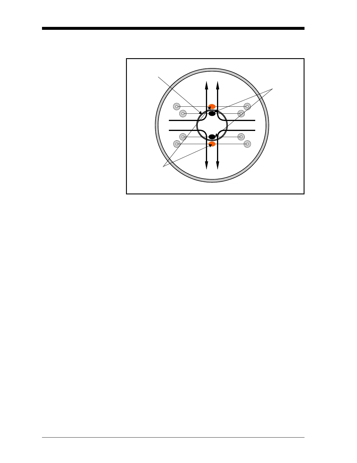
Figure 1-2 below shows the arrangement of the two thermistor pairs.
Figure 1-2: Arrangement of the Thermistor Pairs
A small portion of the sample gas flow is allowed to diffuse from the
lower chamber into the upper chamber of the measurement cell. If the
sample gas contains a paramagnetic gas such as oxygen, it is attracted
to the magnetic field, causing the sample gas pressure to become
locally higher in the center of the chamber. At the same time, the
sample gas pressure is slightly lower near the thermistors because the
high thermistor temperature causes the paramagnetic properties of
oxygen to decrease. This slight gradient in sample gas pressure causes
the sample gas to flow outward from the center of the magnetic field
and over the thermistors. As a result, the inner, wind-generating
thermistors decrease in temperature as they lose heat to the magnetic
wind. This causes a temperature gradient between the cooler inner
thermistors and the warmer outer thermistors.
Figure 1-3 on page 1-5 shows how the two thermistor pairs are
connected in series in an electronic bridge circuit. The bridge circuit
becomes unbalanced as the electrical resistance of the thermistors
changes with temperature. This circuit imbalance causes a voltage
drop, which is proportional to the oxygen concentration in the gas
being measured, to appear across the bridge circuit.
Magnetic Field
Wind Generating
(Cooled)
Thermistors
Induced Gas Flow
Induced Gas Flow
Wind Receiving
(Warmed)
Thermistors