Installation 2-7
September 2007
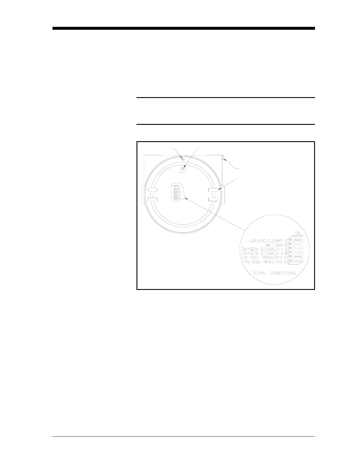
Accessing Terminal Block
TB1
The 24 VDC power input, 4-20 mA analog output, and RS232 digital
output wiring connections are made to terminal block TB1 inside the
XMO2 enclosure (see Figure 2-3 below). To access this terminal
block, loosen the locking set screw and remove the cover from the
transmitter. Then, refer to Figure 2-3 below for the location and pin
designations of terminal block TB1.
Caution!
Do not make any connections to any unused pins on
terminal block TB1.
Figure 2-3: Terminal Block TB1 Connections
Proceed to the next section to begin making connections to terminal
block TB1.
External Ground Screw
Internal Ground Screw
Cover
Set Screw