Installation 2-3
September 2007
A Basic System (cont.) The sample system shown in Figure 2-1 on page 2-2 consists of a
painted steel plate with the following components mounted on it:
• inlet needle valves for sample, zero, and span gas flow regulation
• ball valves for flow selection
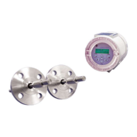
• an XMO2 transmitter
• a sample gas outlet pressure gauge
• a sample gas flowmeter
Other components, such as a pump, a filter/coalescer, or a pressure
regulator could be added to the system if needed.
Mounting the Sample
System
To mount the sample system, complete the following steps:
1. Select a location that is as close as possible to the process
sampling point. The ambient temperature at this location should
be in the range of -20° to +40°C (-4° to +104°F).
IMPORTANT: For locations where the ambient temperature falls
below -20°C (-4°F), install the sample system in a
heated enclosure.
2. Using the mounting holes provided, fasten the sample system to a
convenient vertical surface. The system must be installed in an
orientation that keeps the XMO2 transmitter upright and level to
within ±15°.
3. After the sample system has been mounted, use 1/4” stainless steel
tubing to connect all inlet and outlet lines to the 1/4” tube fittings
on the sample system. The sample line leading from the process to
the sample system should be as short as possible in order to
decrease system lag time and to prevent condensation in the line.
Proceed to the next section to begin wiring the system.
Caution!
Always apply power to the XMO2 transmitter immediately
after installation, especially if it is mounted outdoors or in
a humid area.