5 Assembly and installation
This chapter
contains information and instructions about the assembly and installation
of the valve.
It is addressed to all persons who carry out actions related to the valve.
INFO During assembly and installation, observe chapter
2 Safety
of this Operat-
ing Instructions.
5.1 Notes on installation
The valve can be installed in any position. Steps must be taken to ensure that the valve
housing and the pipe system can drain properly.
If the valve is installed in the horizontal position, pay attention that the vent hole in the
actuator is aligned horizontally on one side.
To avoid damage, ensure that the valve is installed into the pipe system without tension
and no objects remain in the system after assembly (e.g. tools, screws, lubrication oils).
If the valve is installed horizontally, the stress on the valve stem seals is higher than in
the vertical installation position. Therefore, support the actuator and regularly check
the valve for leakage.
5.2 Control top
If the external valves are connected in a control top with several solenoid valves, make
sure that the control air pressure in the main actuator does not fall below the operating
pressure.
5.3 Install the valve with detachable pipe connection
elements
Prerequisites
●
The pipe is drained, and cleaned or rinsed, if necessary
.
●
The
pipe section for the valve to be mounted must be separated from the re-
maining pipe system.
1. Fit valves with detachable pipe connection elements – using suitable connection
ttings – directly into the pipe system.
Þ
Valve is installed.
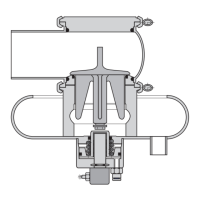
5.4 Install valve with welding ends
WARNING
Spring tension in the valve (NC)
Danger of injury when opening the clamp connections on the actuator or on the
housing as the r
eleased spring pr
etension will suddenly lift the actuator.
●
Therefore, release the spring tension before detaching the clamp connection by
pressurising the actuator with compressed air at max. 8 bar.
5.1 Notes on installation - 35 / 104
 Loading...