Tools
●
Hex key, a/f 3
●
Jaw wr
ench a/f13
●
Torque screwdriver
●
Open-end plug tool size a/f13
●
Tool bit 6.3-PH2 Philips
●
Tool bit 6.3 size 3 hex
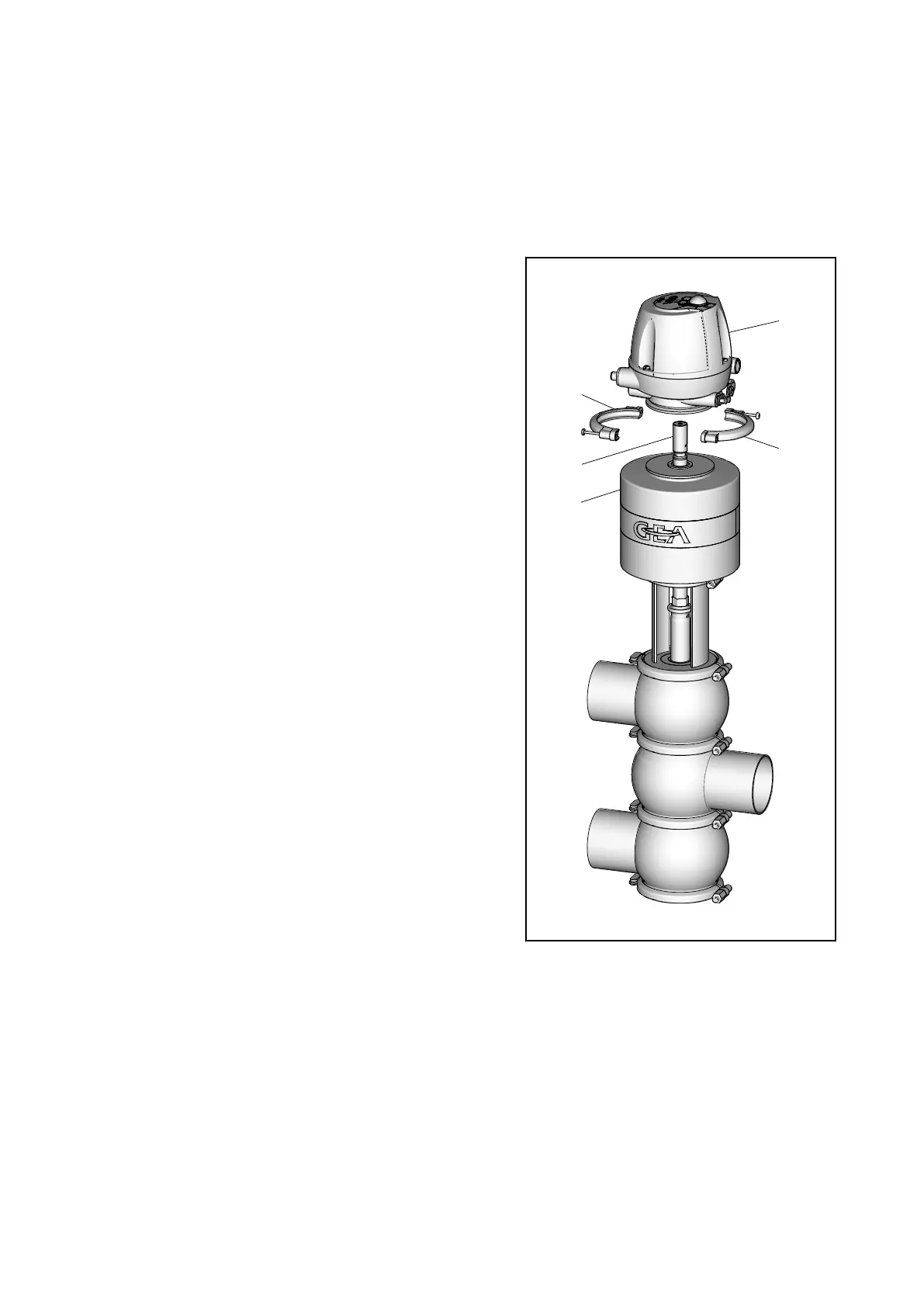
1. Screw the switch bar (1) into the ac-
tuator (A) using a jaw wrench.
®
Observe torques, see
9.6.1 Tight-
ening torques
.
2. Place the control top (B) onto the
switch bar (1) from above.
3. Mount the half-rings (B12) on the
control top (B).
®
Ensure that the half-rings are
mounted correctly!
Observe torques, see
9.6.1 Tight-
ening torques
.
Þ
Contr
ol top is
tted.
70 / 104 - 9.6 Installing the valve
0000000881 - 001 - EN-GB
 Loading...