6
in.xe TechBook
The following material
is recommended:
4- # 10 screws of
appropriate length with
round, truss or pan
head.
4- washers .5” OD x
.0625” thickness (12 mm
OD x
1.5 mm)
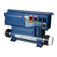
Select the most appropria-
te location on the floor for
spa pack and firmly attach
guide plate to wooden
base with 2 screws backed
by 2 washers.
in.k200 dimensions:
2"
(51 mm)
4.75"
(120 mm)
1.7"
(43 mm)
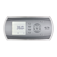
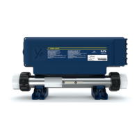
Features:
LED display
4 Keys
8 light indicators
in.link connector
Mechanical Specs:
Weight:
0.9 lb (0.41 kg)
Dimensions (W x H x D):
Front panel: 4.75" x 2" x 1.7"
(120 mm x 51 mm x 43 mm)
Soft gasket
Approvals:
UV resistance (ASMTD4329)
UL, CSA, TUV and CE
Now firmly attach unit to
wooden base by using
the remaining 2 screws
backed by 2 washers to
attach the front of the feet.
Note: The spa pack must
be installed at least
4" (52 mm) above
potential flood level.
If floor is on ground level,
pack should be raised at
least 4" (52 mm).
Important!
Please note that
countersunk screws
should not be used as
they can damage the
power box support.
Slide back side of the
unit's feet into the guide
plate. It should easily slide
into place.
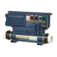
Floor installation procedure
in.xe installation
4"
Warning!
Beware the application of some products
commonly used against corrosion (such as WD-40
family products) as they could damage the power
box, due to a negative chemical reaction between
some industrial oils and its plastic enclosure. Any
other materials which may come in contact with
the enclosure must be carefully evaluated under
end use conditions for compatibility.
 Loading...