13
1.3. 650 Controller
Main features
• Operator interface with large LCD Display, customi-
zable, with choice of colors
• Scrolling diagnostics messages, configurable, in the
selected language
• Easy, guided configuration, copy/paste parameters
even with power off
• Preventive maintenance with energy counters (kWh)
and load switching
• 16 function block applications
• Timer, setpoint and algorithm programmer for control-
ling motorized valves
• Advanced tuning of control parameters
• Different password levels
• Universal input configurable for thermocouples, resi-
stance thermometers, linear inputs
• Input from remote setpoint
• Relay, logic, isolated analog outputs
• Up to two TA inputs for interrupted load diagnostics
• RS485 serial communication in Modbus RTU
• Removable faceplate for immediate replacement
• Accuracy 0.2%, sampling time 60 ms
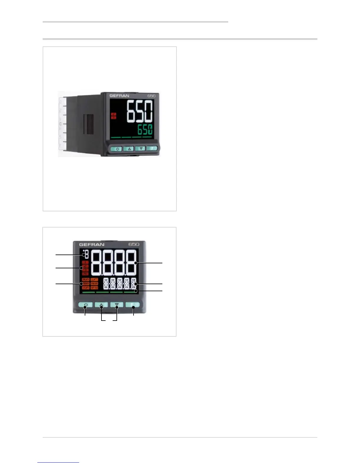
1.3.1. Display and keys
Figure 1 - Description of 650 display and keys
1. Temperature unit of measurement or number of program
running.
2. State of outputs OUT1, OU2, OUT3, OUT4.
3. Controller function states:
• RUN = setpoint programmer active;
• _/- = setpoint ramp active;
• TUN = PID parameters tuning active;
• MAN = manual/automatic (off = automatic control,
on = manual control);
• REM = remote setpoint enabled;
• SP1/2 = setpoint active (off = setpoint 1,
on = setpoint 2).
4. Work mode key (manual/automatic) in standard mode.
A function can be assigned via parameter but1.
The key is active only when the display shows the pro-
cess variable
5. Up/down keys: raise/lower the value of the parameter
displayed on the SV or PV display.
6. F key: lets you navigate among controller menus and
parameters. Confirms the parameter value and selects
the next parameter.
7. Key pressed signals.
8. SV display: setpoint value, description of parameters,
diagnostics and alarm messages.
Configurable with parameter dS.SP (default = setpoint).
9. PV display: process variable, parameter values.
1
2
3
4 5 6
7
8
9
Dimensions 48 × 48 × 80 mm (1/16 DIN)
1. GENERAL DESCRIPTION