137
6
5
4
3
2
1
7
8
9
10
11
12
19
20
21
22
23
24
+
-
T/C
L
N
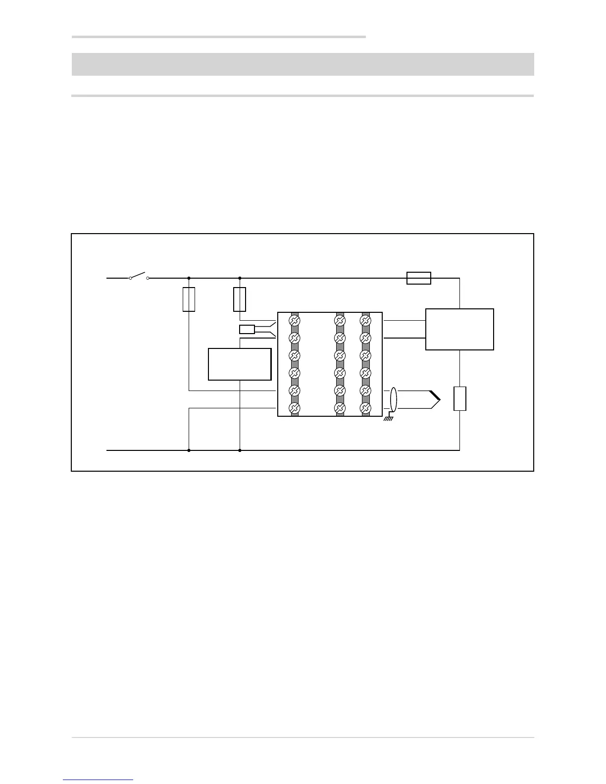
5. Examples and applicative notes
5. EXAMPLES AND APPLICATION NOTES
5.1. Heat/cool control application
A 650 controller (model 650–D-R00-00000-1) controls a
heating element via a solid-state relay connected to a
logic output.
A TC sensor measures the temperature.
Each branch of the circuit is protected by a fuse.
The cooling or alarm relay is protected by a snubber.
The following diagram shows the various connections.
One switch can control more than one controller.
With Quick Configuration you set:
• sensor type (TC);
• unit of measurement of temperature (°C);
• the logic output function (HEAT);
• the relay output function (ALRM1);
• the setpoint, i.e. the temperature to be maintained
(SETP);
• the temperature value that trips the alarm (ALRM1).
5.1.1. Connection diagram
Heating element
fuse
Controller fuse
Solid state
relay
Heating
element
650 Controller
Fuse relay cooling
or alarm
Snubber
Cooling or
alarm relay