162
7. OPERATOR GUIDE
7.4. Operation as programmer
7.4.1. Activating the programmer
To enable the Programmer function, set parameter PROGR
= ON on the MODE menu.
On the user menu, the parameter P.STAT, which lets you
display/control the programmer, is inserted by default.
The user menu is available if QUICK = OFF
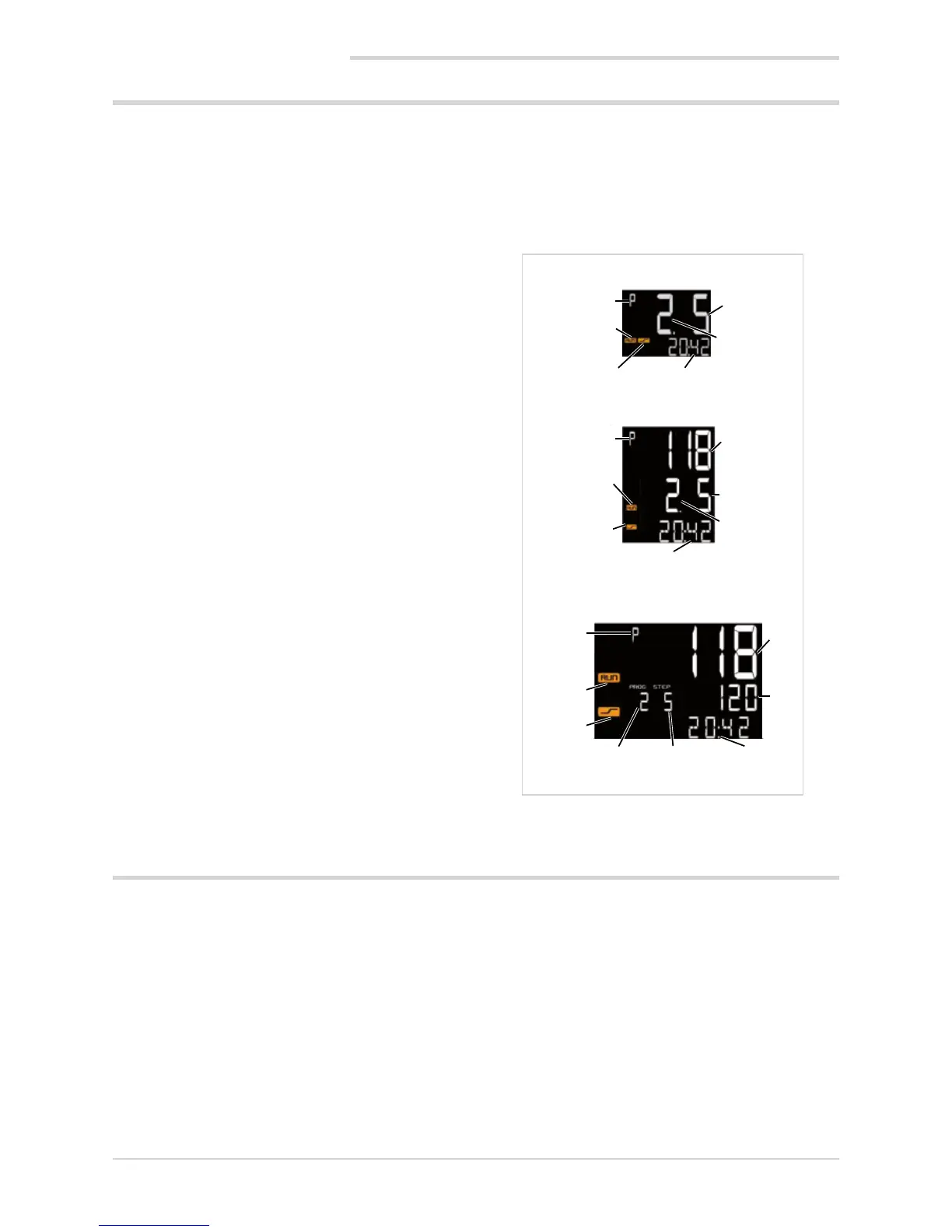
7.4.2. Display messages
The different controller models display programmer state in-
formation in different ways.
The following examples show how the identical information
is displayed on the 650, 1250 and 1350 controllers.
As opposed to the model 650, the models 1250 and 1350
also show the process variable PV value.
As opposed to the other two models, the model 1350 also
shows the setpoint value of the active step.
1. Indication of programmer state. When on, the program-
mer is on.
2. Number of program running (in example: number 2).
3. Number of program step running (in example: number 5).
4. RUN LED: when on, indicates that program is running;
when flashing, indicates that program is in STOP, END
or HOLD and that time base is stopped.
5. RAMP LED: when on, indicates that programmer is
running ramp segment of step; if off, it is in hold seg-
ment of step or at end of program (in example: running
ramp of step 5).
6. Current time of segment (ramp or hold) of step. The
time value depends on the set time base, hh:mm
or mm:ss (in example: time lapsed is 20 minutes 42
seconds).
7. Process variable PV (in example: 118).
8. Setpoint of current step, i.e., value to be reached (in
example: 120).
1
1
4
4
5
5
1
4
5
6
6
6
3
7
8
7
3
3
2
2
2
650
1250
1350
7.5. Errors during operation
If errors occur during normal operation, the display shows:
• the identifying code of the error on the PV display;
• the value of the setpoint or of the control output on the
SV display.
If provided during configuration of the controller, a specific
scrolling message appears on the SV display (model 650) or
on the F display (models 1250 and 1350).
The most common error messages are:
Lou Process variable is below minimum scale limit (para-
meter LO.SCL on I.MAIN).
High Process variable is above maximum scale limit (para-
meter HI.SCL on I.MAIN).
Err PT100 in short circuit or input values below minimum
limits (for example, thermocouple with incorrect con-
nection) or 4...20 mA transmitter broken or not powe-
red.
Sbr Sensor broken or input values above maximum limit.