1
CONTENTS ..........................................................................1
Introduction .........................................................................7
Device data ......................................................................................7
Warnings and safety ......................................................................... 7
Typographical conventions used in this manual ..............................8
Glossary ...........................................................................................8
Disclaimer .........................................................................................9
Copyright ..........................................................................................9
1. General description ................................................11
1.1. Profile ...................................................................................11
1.2. Differences among models ..................................................12
1.3. 650 Controller .......................................................................13
1.3.1. Display and keys ........................................................ 13
1.3.2. Drilling dimensions and templates ............................. 14
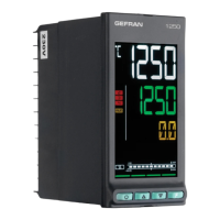
1.4. 1250 Controller .....................................................................15
1.4.1. Display and keys ........................................................ 15
1.4.2. Drilling dimensions and templates ............................. 16
1.5. 1350 Controller .....................................................................17
1.5.1. Display and keys ........................................................ 17
1.5.2. Drilling dimensions and templates ............................. 18
2. Installation ...............................................................19
2.1. Mounting the controller ........................................................19
2.1.1. General installation rules ............................................19
2.1.2. Drilling dimensions ..................................................... 19
2.1.3. Protection against infiltration of dust ............................
.................................................................................and
water ..........................................................................19
2.1.4. Vibrations ...................................................................20
2.1.5. Minimum space for ventilation ................................... 20
2.1.6. Positioning .................................................................20
2.1.7. Fastening to the panel ...............................................20
2.2. Connections .........................................................................21
2.2.1. General rules for connections .................................... 21
2.2.2. Electromagnetic compatibility (EMC) ........................ 21
2.2.3. Cables ........................................................................ 21
2.2.4. Power supply .............................................................21
2.2.5. Connecting inputs and outputs .................................22
2.3. 650 connection diagrams .....................................................23
2.3.1. General diagram.........................................................23
2.3.2. Power supply .............................................................24
2.3.3. Inputs .........................................................................24
2.3.4. Outputs ......................................................................24
2.3.5. Options ......................................................................25
2.4. 1250 - 1350 connection diagrams .......................................27
2.4.1. General diagram.........................................................27
2.4.2. Power supply .............................................................28
2.4.3. Inputs .........................................................................28
2.4.4. Outputs ......................................................................28
2.4.5. Digital inputs ..............................................................29
2.4.6. Serial line ....................................................................29
2.4.7. CT Inputs ...................................................................29
2.4.8. Remote setpoint input................................................30
2.4.9. Analog output ............................................................30
2.5. RS485 serial connection diagram ........................................31
3. Commissioning .......................................................33
3.1. Information on displays and use of keys..............................33
3.1.1. Navigating the menus ................................................33
3.1.2. Displays ......................................................................33
3.1.2.1. Display characters ............................................................. 33
3.1.2.2. Scrolling messages ............................................................ 34
3.2. Sequence at power-on ......................................................... 34
CONTENTS
CONTENTS
3.3. First power-on ......................................................................35
3.3.1. Fast configuration ......................................................35
3.4. Setting up quick configuration .............................................39
3.4.1. Setting up the Alarm .................................................39
3.4.2. Setting up the Heater Break Alarm ............................40
3.4.3. Setting up the PID ...................................................... 41
4. Configuration .......................................................... 43
4.1. Programming/Configuration Menu .......................................43
4.1.1. First: know what you’re doing .................................... 43
4.1.2. Passwords .................................................................43
4.2. Main menu ...........................................................................44
4.3. Legend for submenus and parameters ................................ 45
4.3.1. Submenu ....................................................................45
4.3.2. Parameters .................................................................45
4.4. INFO Submenu - information display ...................................46
4.4.1. SW.VER - Versione software ...................................... 47
4.4.2. CODE - Identifying code of controller ........................ 47
4.4.3. ERROR - Main input error ..........................................47
4.4.4. SAP.C - SAP code ......................................................47
4.4.5. SEr.n - Serial number of controller ............................. 47
4.4.6. xxxxx - Model of controller ........................................48
4.4.7. xxxxx - Type of controller ...........................................48
4.4.8. L.FUNC - Option Logic Functions available ..............48
4.4.9. IN.SPR - Remote setpoint input available .................48
4.4.10. OUT.A1 - Analog output 1 available ...........................48
4.4.11. CTx - Current transformer input available..................49
4.4.12. x.IN.DG - Digital input available ................................. 49
4.4.13. RS485 - RS485 serial port available ..........................49
4.4.14. Out1 - Type of output 1 ..............................................49
4.4.15. Out2 - Type of output 2 .............................................49
4.4.16. Out3 - Type of output 3 .............................................50
4.4.17. Out4 - Type of output 4 .............................................50
4.4.18. OUT1.S - Number of switchings output 1 ...............50
4.4.19. OUT2.S - Number of switchings output 2 ................50
4.4.20. OUT3.S - Number of switchings output 3 ...............50
4.4.21. OUT4.S - Number of switchings output 3 ...............51
4.4.22. T.DAYS - Total working days ...................................... 51
4.4.23. P.DAYS - Partial working days ...................................51
4.4.24. T.INT - Internal temperature of controller ................... 51
4.4.25. T.MIN - Minimum internal temperature of the controller
51
4.4.26. T.MAX - Maximum internal temperature of the control-
ler ...............................................................................52
4.4.27. tiME - Internal time .....................................................52
4.4.28. dAtE - Internal date .................................................... 52
4.5. PR.OPT Submenu - Configuring programs..........................53
4.5.1. PR.OPT - Selecting program .....................................54
4.5.2. FI.STP - Number of first step assigned to program ... 54
4.5.3. LA.STP - Number of last step assigned to program .. 54
4.5.4. Strt - Restart mode ....................................................54
4.5.5. RST.SP - Type of control after program restart ..........54
4.5.6. WAIT.S - Option to start execution of program ..........55
4.5.7. End - Action at end of program .................................55
4.5.8. LIMIT - Limitation of step duration .............................55
4.6. PR.STP Submenu - Configuration of program steps ........... 55
4.6.1. PR.STP - Programming step......................................57
4.6.2. SETP - Programming step setpoint ..........................57
4.6.3. RAMP.T - Step time ramp ..........................................57
4.6.4. HOLD.T - Hold time in step........................................57
4.6.5. HBB - Enable Hold Back Band function .................... 57
4.6.6. BAND - Maximum deviation for HBB.........................58
4.6.7. HBB.R - Enabling HBB during ramp .......................... 58
4.6.8. HBB.H - Enabling HBB during hold ........................... 58
4.6.9. HBB2 - Enabling HBB with respect to I.SPR ............. 58
4.6.10. S.SP.EN - Enabling retransmission of setpoint ..........58
4.6.11. SUB.SP - Setpoint value of slaved controller ............59
4.6.12. S.RM.EN - Enabling ramp for slaved controller ......... 59

 Loading...