ADV200 • Functions description and parameters list 31
zero to the maximum value set in the Full scale speed (5.22). On the other hand, the deceleration times (6.2,
6.4, 6.6, 6.8 ) are expressed as the time necessary to bring the frequency from the maximum value set in the
Full scale speed (5.22) parameter to zero. Each of the 4 available ramp selections can be selected using one
or two digital inputs programmed as Multi ramp sel.
Menu PAR Description UM Type FB BIT Def Min Max Acc Mod
6.9 720 Ramp type ENUM Linear 0 3 ERWZ FVS
This parameter denes the ramp shape (linear/S-shape). It can only be modied with the drive disabled.
0 Linear
1 S-Shape
2 Bypass
3 Off
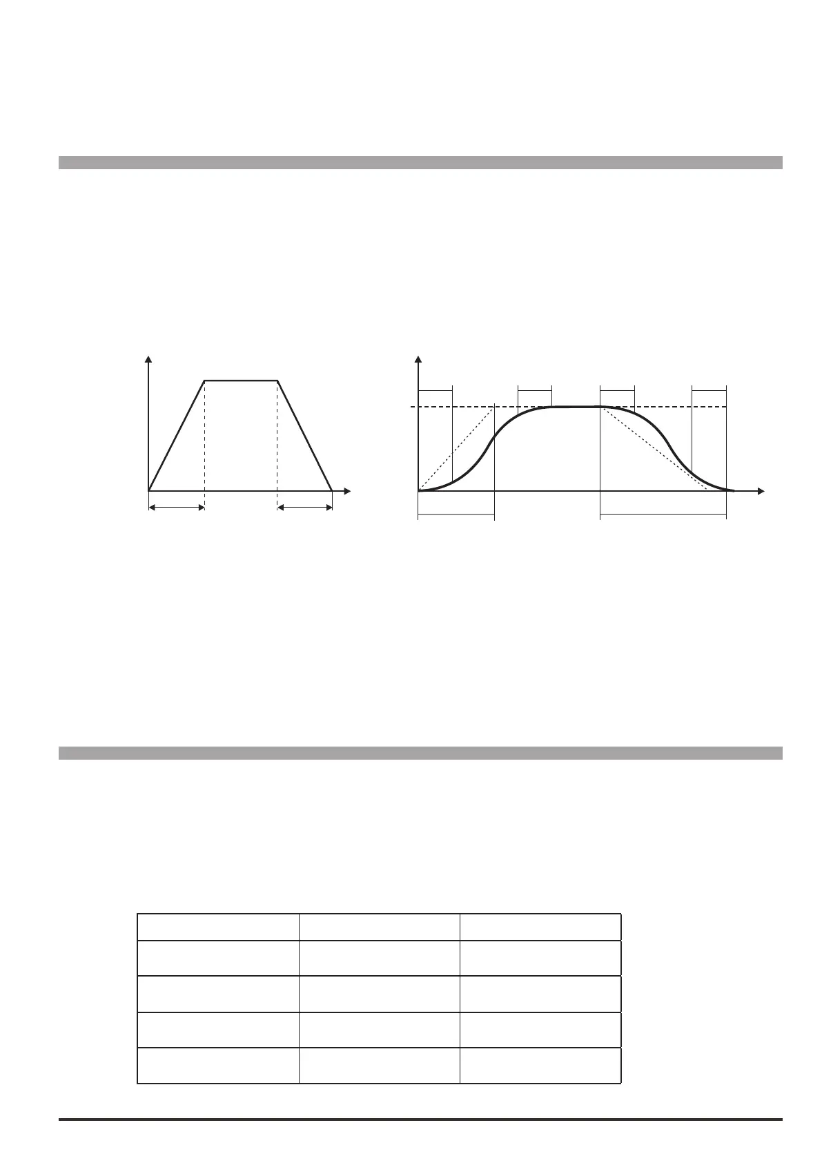
ACC TIME DEC TIME
6.1 6.2
T
6.13 6.13 6.14 6.14
0 = Linear 1 = S-Shape
When linear ramps are set (Linear) the motor speed varies in a way that is directly in proportion to
the frequency.
When S-shape ramps are set (S-Shape) it is possible to avoid sudden mechanical variations in the system at
the beginning and end of the acceleration and deceleration phase.
The ramp time, meaning the time necessary to accelerate from zero to the maximum frequency value
set, is given by the sum of the linear ramp time and that of the associated Jerks (see par. 6.13 – 6.20).
The Bypass excludes the ramp circuit and the reference is brought directly to the speed regulator input.
With Off the ramp reference is set to zero.
Menu PAR Description UM Type FB BIT Def Min Max Acc Mod
6.10 722 Multi ramp sel 0 src LINK 6000 0 16384 ERWZ FVS
6.11 724 Multi ramp sel 1 src LINK 6000 0 16384 ERWZ FVS
1 or 2 digital inputs can be used to select one of the 4 available sets of ramps.
The origin (source) of the command to enable the ramp selection function can be selected from the “L_DIG-
SEL2” selection list.
The following table describes the ramp selection procedure:
Enabled ramp time Multi ramp sel 0 Multi ramp sel 1
Acceleration time 0
Deceleration time 0
0 0
Acceleration time 1
Deceleration time 1
1 0
Acceleration time 2
Deceleration time 2
0 1
Acceleration time 3
Deceleration time 3
1 1