42 ADV200 • Functions description and parameters list
Menu PAR Description UM Type FB BIT Def Min Max Acc Mod
8.13 894 Mpot output mon rpm INT16 16/32 0 0 0 ER FVS
The value of the output of the motor potentiometer function is displayed.
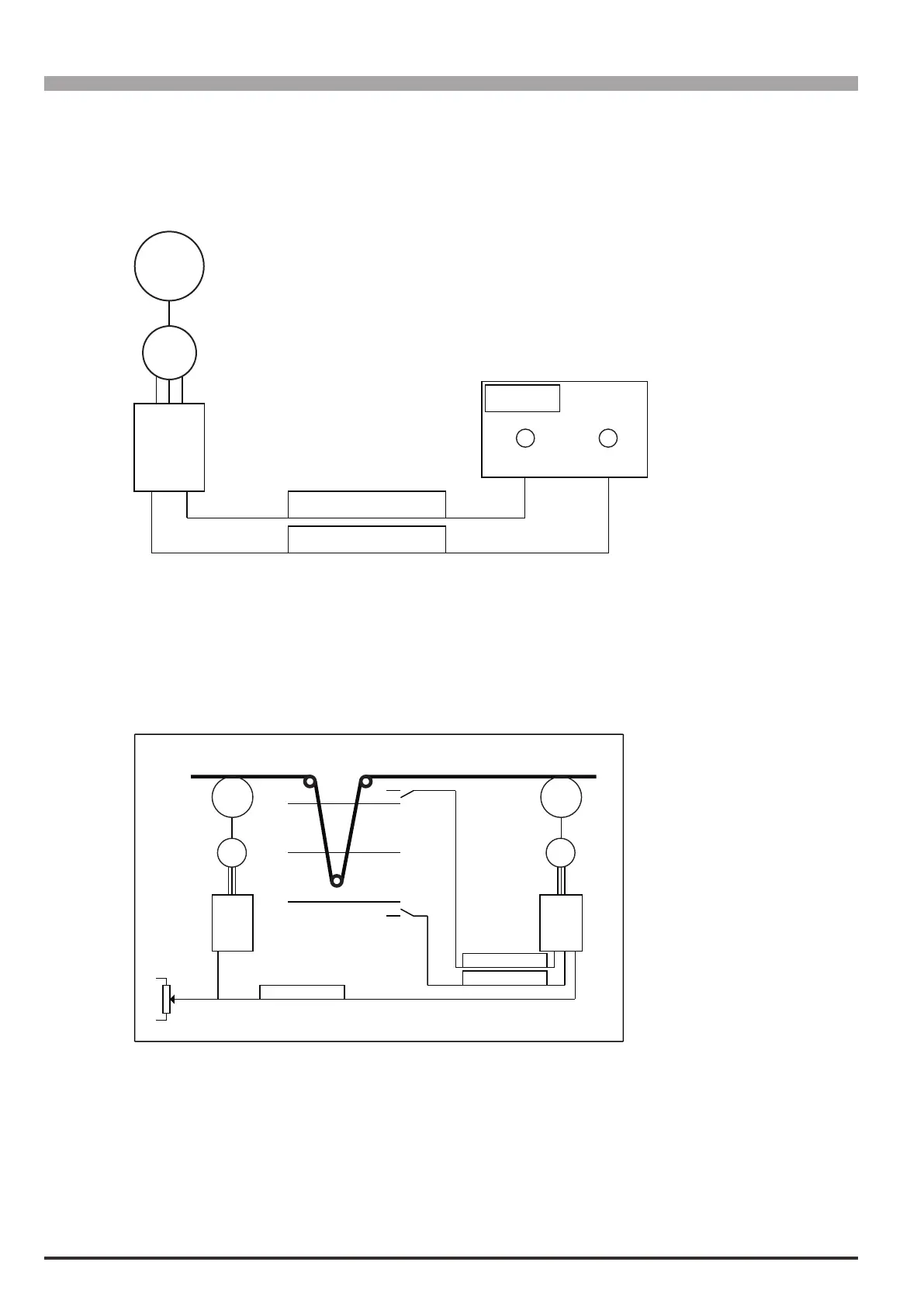
Two examples of application of the motor potentiometer function are shown below.
Manual speed control with command sent from external control desk.
M
ADV
Mpot up
Mpot down
UP DOWN
Speed
Command console
The Up and Down keys are used to adjust the speed of a motor.
For ne-tuning of the speed reference value the recommended settings are Mpot Mode = Fine&Follow or
Fine&Last Val. Each time they are pressed for 1 second, the speed increases by 1 rpm. For an immediate ef-
fect on motor speed, the Acceleration time and Deceleration time parameters should be set to short times.
Automatic speed control for rudimentary dancer control.
M
ADV
1
M
ADV
2
0V
10V
Center
Bottom
Top
24V
24V
Mpot up
Mpot down
Ramp ref
The limit switches at the ends of dancer travel ranges are connected to the Up and Down commands in the mo-
tor potentiometer function. If the dancer presses the bottom limit switch, this means motor 2 is running slowly
and the Up command must be sent. If the dancer presses the top limit switch, this means motor 2 is running
quickly and the Down command must be sent.
Connect the line reference to Ramp ref 1 src on both drives, connect the motor potentiometer function output
to Speed ref 1 src on drive 2.
To change the motor speed immediately, the recommended settings are Mpot Mode = Ramp&Follow or
Rampa&Last Val.