www.gemu-group.com 17 / 71 GEMÜ 1435 ePos
11.2.3 Installing the adapter
With some mounting kits it is necessary to install an adapter
as well. These adapters are included with the required mount-
ing kits. Valves with a normally open and double acting con-
trol function (code 2+3) also include additional O-rings (1+2).
NOTICE
● The adapter only needs to be mounted if included.
● There are two variants for mounting the adapter.
- One adapter included with or without mounting bracket.
- Two adapters included (identical or different design) with
mounting bracket.
1. Move the actuator to the closed position.
2. Place O-rings 1 and 2 into adapter 3.
If one adapter is included:
3. Screw the adapter 3 into the actuator opening as far as it
will go and tighten.
ð In some cases, if included, a mounting bracket may
also need to be mounted under the adapter (see
chapter 10.6, Direct mounting with mounting bracket
type 2). Otherwise, the mounting bracket included is
mounted later.
If two adapters are included with mounting bracket:
4. The mounting bracket 4 is fixed through the travel sensor
later.
5. Screw the appropriate adapter 3.1 into the actuator open-
ing as far as it will go and tighten.
ð The mounting bracket is mounted later with the
second adapter (see chapter 10.6, Direct mounting
with mounting bracket type 4).
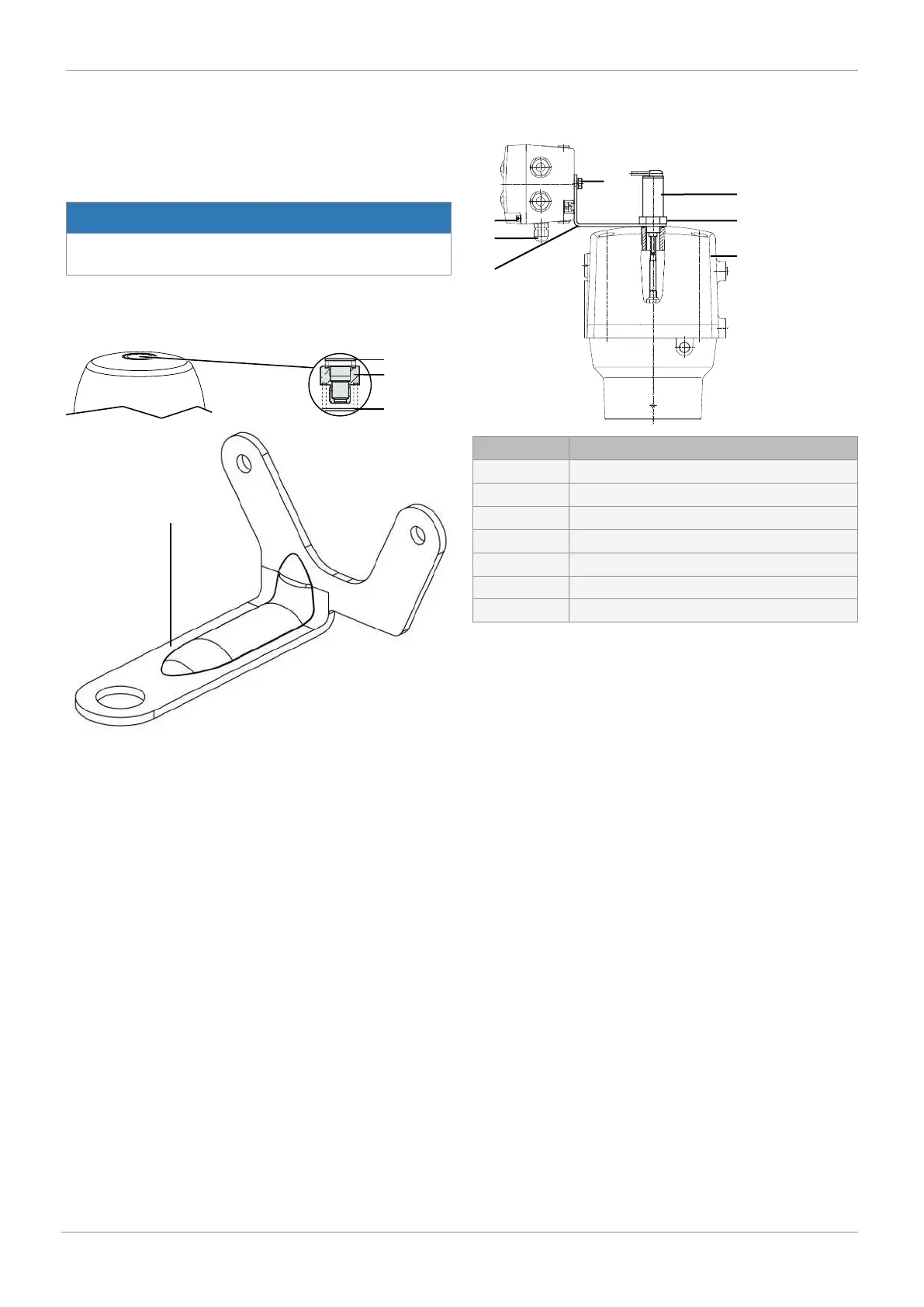
11.2.4 Direct mounting
Item Name
1 Mounting bracket
2 Actuator
3 Travel sensor
4 Hexagon
5 M6 screws
6 M12 cable gland
7 M4 screws
1. Mount the travel sensor mounting kit.
2. Move the actuator to the open position.
3. Depending on the version, attach the mounting bracket 1
to the actuator 2 or adapter and guide the travel sensor 3
through the mounting bracket as far as it will go into the
actuator opening and screw in place in the clockwise dir-
ection against the initial spring tension.
11 Assembly