www.gemu-group.com16 / 71GEMÜ 1435 ePos
10 Manufacturer's information
10 Manufacturer's information
10.1 Delivery
● Check that all parts are present and check for any damage
immediately upon receipt.
The product's performance is tested at the factory. The scope
of delivery is apparent from the dispatch documents and the
design from the order number.
10.2 Transport
1. Only transport the product by suitable means. Do not drop.
Handle carefully.
2. After the installation dispose of transport packaging ma-
terial according to relevant local or national disposal regu-
lations / environmental protection laws.
10.3 Storage
1. Store the product free from dust and moisture in its ori-
ginal packaging.
2. Avoid UV rays and direct sunlight.
3. Do not exceed the maximum storage temperature (see
chapter "Technical data").
4. Do not store solvents, chemicals, acids, fuels or similar
fluids in the same room as GEMÜ products and their spare
parts.
11 Assembly
11.1 Information for use in damp conditions
1. The product must not be used outdoors without a heating
element. The version with heating element may only be
used outdoors in a rain-protected area.
2. The product must be protected from the direct influence
of rain water.
11.2 Assembly on linear actuators
11.2.1 Preparations for assembly to the valve
1. Move the actuator A into zero position (actuator vented).
2. Remove optical position indicator 2 and / or protective cap
1 from the actuator top.
11.2.2 Linear travel sensor mounting kit assembly for remote
mounting
CAUTION
Pretensioned spring!
▶ Damage to the device.
● Slowly release the tension in the spring.
CAUTION
Do not scratch the spindle!
▶ A damaged spindle surface may cause failure of the
travel sensor.
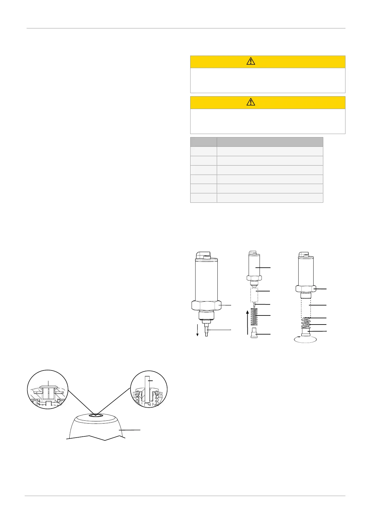
Item Name
1 Travel sensor
2 Spindle
3 Spring
4 Operating bush
5 Guide bush*
6 Threaded adapter**
*Included depending on version
**If a threaded adapter is included, it must be screwed into
the actuator top of the process valve
The process described below refers to the mounting kit
mounting for direct and remote mounting.
1. Pull the spindle 2 out of the travel sensor 1.
2. If included, push the guide bush 5 taper over the spindle 2
first.
3. Push the spring 3 over the spindle 2 and secure with the
operating bush 4.
4. Tighten the operating bush 4 by turning it clockwise.
5. Push in the spindle 2 as far as it will go on the spring 3
and then slowly release the pressure on the spring 3.