www.gemu-group.com18 / 71GEMÜ 1435 ePos
11 Assembly
NOTICE
Wrong mounting kit
▶ If no initial spring tension can be felt, it may be the case
that the wrong mounting kit with too short an operating
bush has been used.
▶ If the spring locks and the positioner cannot be correctly
mounted on the valve, it may be the case that the wrong
mounting kit with too long an operating bush has been
used or that a required adapter has not been used.
● In both cases, check that the mounting kit parts are being
used correctly and in their entirety.
4. Tighten the travel sensor 3 using a suitable open-end
wrench WAF 27.
5. Attach the positioner to the mounting bracket 1 with two
M6 screws 5.
6. Loosen the M4 screws 7 on the housing cover and swing
the cover open.
7. Feed the connection cable of the travel sensor into the
cable gland 6 of the positioner and connect to the terminal
board as shown in the wiring diagram.
8. Then tighten the cable gland. The cable must be held
firmly on all sides.
9. Connect the pneumatic supply to the positioner and con-
nect to the process valve.
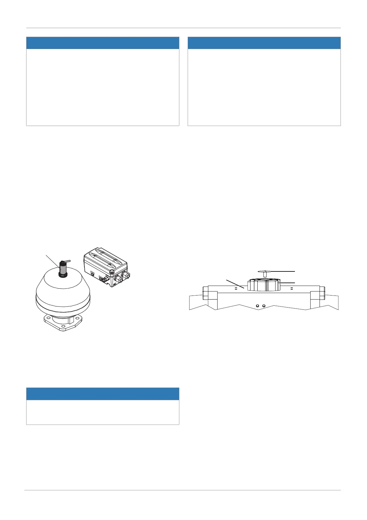
11.2.5 Remote mounting
1. Mount the travel sensor mounting kit.
2. Move the actuator to the open position.
3. Guide the travel sensor 3 as far as it will go into the actu-
ator opening and screw it in clockwise against the initial
spring tension.
4. Fit the positioner in a suitable location.
NOTICE
Mounting bracket
▶ The GEMÜ 1445 000 ZMP mounting bracket, which is
available separately, can be used for this.
NOTICE
Wrong mounting kit
▶ If no initial spring tension can be felt, it may be the case
that the wrong mounting kit with too short an operating
bush has been used.
▶ If the spring locks and the positioner cannot be correctly
mounted on the valve, it may be the case that the wrong
mounting kit with too long an operating bush has been
used or that a required adapter has not been used.
● In both cases, check that the mounting kit parts are being
used correctly and in their entirety.
5. Tighten the travel sensor 3 using a suitable open-end
wrench WAF 27.
6. Connect the travel sensor 3 to the positioner electrically.
7. Loosen the M4 screws 7 on the housing cover and swing
the cover open.
8. Feed the connection cable of the travel sensor into the
cable gland 6 of the positioner and connect to the terminal
board as shown in the wiring diagram.
9. Then tighten the cable gland. The cable must be held
firmly on all sides.
10. Connect the pneumatic supply to the positioner and con-
nect to the process valve.
11.3 Assembly on quarter turn actuators
11.3.1 Preparations for assembly to the valve (quarter turn
actuator)
1. Move the actuator A into zero position (actuator vented).
2. Remove the screw 1 from the trigger cam 2.