www.gemu-group.com 19 / 71 GEMÜ 1435 ePos
11.3.2 Rotary travel sensor mounting kit assembly
NOTICE
Determining the rotational direction of the actuator
▶ When viewed from above, the rotational direction of the
actuator must be anticlockwise, when the actuator moves
from the CLOSED to the OPEN position. In cases where
the actuator turns in a clockwise direction, the travel
sensor's end position, contrary to given instructions,
needs to be in the opposite direction.
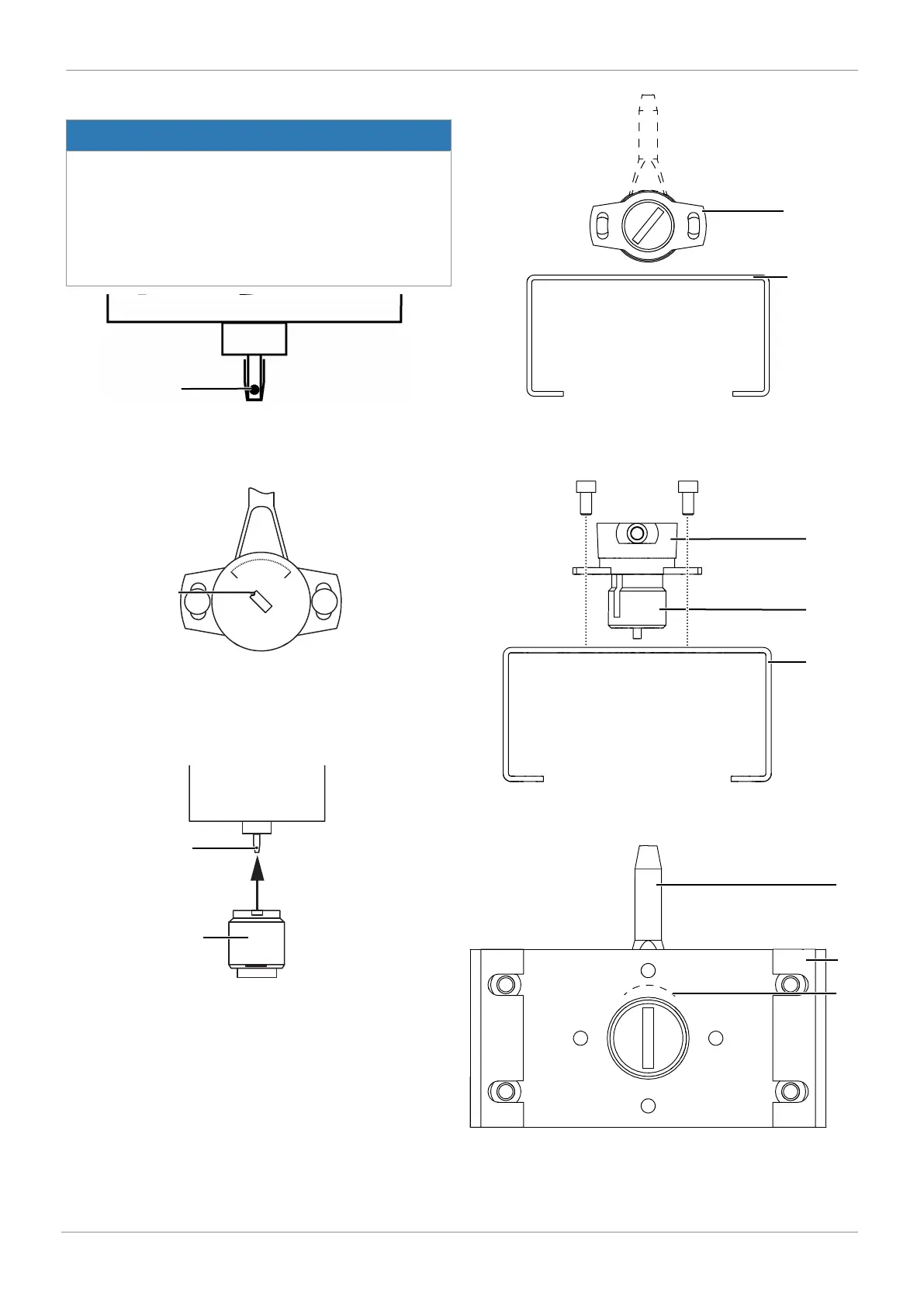
1. The shaft of the rotary travel sensor is provided with a
marking 2.
2. Set the marking 2 so that it is correctly aligned with the 0°
position on the underside of the travel sensor housing.
The 0° position is located on the left-hand side of the
cable exit (the electrical operating range is located in the
travel range between the 0° and 90° positions).
3. Place the adapter 4 onto the shaft of the rotary travel
sensor 2 without twisting the shaft.
4. Mount the black housing of the rotary travel sensor 4 in
parallel to the mounting bracket 6 in a longitudinal direc-
tion.
5. Mount the external rotary travel sensor 7 with the adapter
4 on the mounting bracket 6.
6. Note the direction of the scale 8.
ð View from below of the travel sensor 7 with mounting
bracket 6.
11 Assembly