www.gemu-group.com38 / 71GEMÜ 1435 ePos
17 System mode ADVANCED
NOTICE
Increased wear due to low value
▶ The level of the system deviation should always corres-
pond to the requirements of the valve and the control cir-
cuit. A value of < 1.0% is not recommended, since this
could cause oscillating control characteristics (e.g. for
actuators with discontinuous movement profiles). This
could put a great deal of stress on the internal pilot
valves.
▶ The following principle applies: The smaller the set value,
the greater the wear and the shorter the service life.
Therefore, the value should only be set to the exact value
required.
43: Prop Gain
Proportional amplification
Adjusting the proportional amplification Kp
Kp = 0.1...100.0
The level of amplification should always correspond to the re-
quirements of the valve and the control circuit. The optimum
setting is determined during automatic initialization but must
be moved out of adjustment later if necessary.
The behaviour of the positioner is influenced as follows:
Prop Gain
Set value > determined value Set value < determined value
The positioner controls faster
(but tends to oscillate).
The positioner controls
slower.
The set value is achieved in
larger steps by increasing the
correcting variable.
The set value is achieved in
smaller steps by decreasing
the correcting variable.
Control is less accurate. Control is more accurate.
44: Deriv Time
Derivative action time
Adjusting the derivative action time Tv (time by which a spe-
cific correcting variable is reached earlier because of the D
component than with a pure P-positioner)
Tv = 0.00 s...10.00 s
46: Release VXX
Status of the current software version V X.X.X.X
Selection of operator interface:
- CLASSIC:
Menu configuration as described in chapter CLASSIC sys-
tem mode (see “System mode CLASSIC“, page31).
- ADVANCED:
Menu configuration as described in chapter ADVANCED
system mode (see “System mode ADVANCED“, page38).
17 System mode ADVANCED
The ADVANCED system mode offers extended diagnostic fa-
cilities. All available parameters are divided into various cat-
egories and stored in various submenus. A large number of
additional parameters are also available, providing additional
information and settings.
NOTICE
Voltage cutoff
▶ After a voltage cutoff, the product always starts in the op-
erating mode which was previously set in the Mode para-
meter.
17.1 Menu level
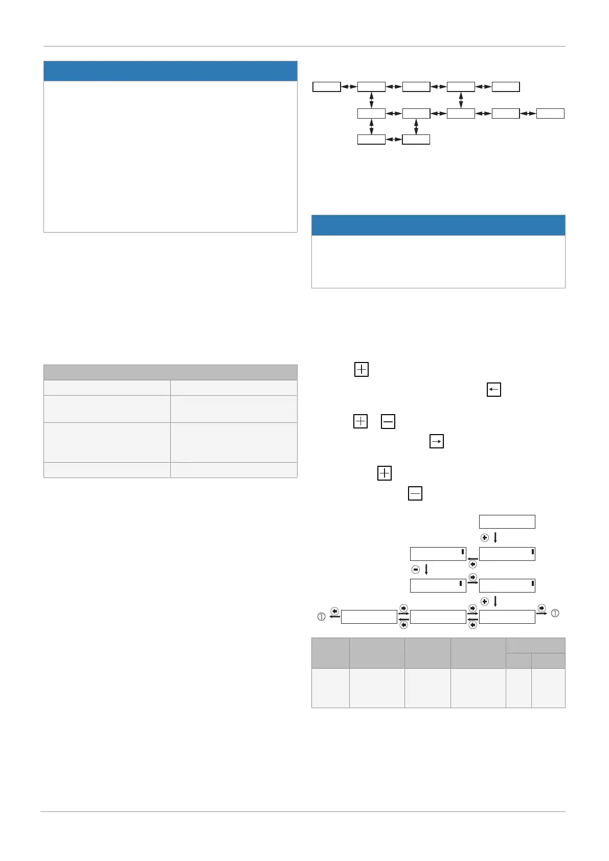
17.1.1 Select operating mode (Mode)
In this parameter, the AUTO or MANUAL operating mode is
selected.
Press the key to jump to the change to the set value. This
is indicated by two brackets. Then use the key to move
the cursor below the value to be changed and adjust the value
using the or key. Then move the cursor below the
right-hand bracket using the key. The message OK now
appears in the bottom line of the display. This is now con-
firmed with the key. Alternatively, the change can be dis-
carded by pressing the (ESC) key.
Mode [ Manual]
<- OK ESC
Mode Manual
Mode [ Manual]
<- -> + -
Mode [ Auto ]
<- -> + -
Mode [ Auto ]
<- OK ESC
Mode Auto
A: W 50.0 : X 50.0 SETUP
Display Function Value
range
Default
setting
Active level
Read Edit
Mode
1)
Select
operating
mode
AUTO,
MAN, OFF
AUTO 0 3
1) Only available after initialization has been carried out