www.gemu-group.com 37 / 71 GEMÜ 1435 ePos
25: SetP Ramp
Set value ramp
The set value ramp is effective during automatic operation
and limits the speed of change of the effective set value.
When switching over from manual to automatic operation, the
effective set value is matched to the set value on the device
via the set value ramp.
In the position SetP Ramp = AUTO, the slower of the two
travel times which have been established during initialization
is used for the set value ramp.
26: Split Start
Set value split range start
27: Split End
Set value range
controller 1
Set value range
controller 2
Set value
Stroke
Set value split range end
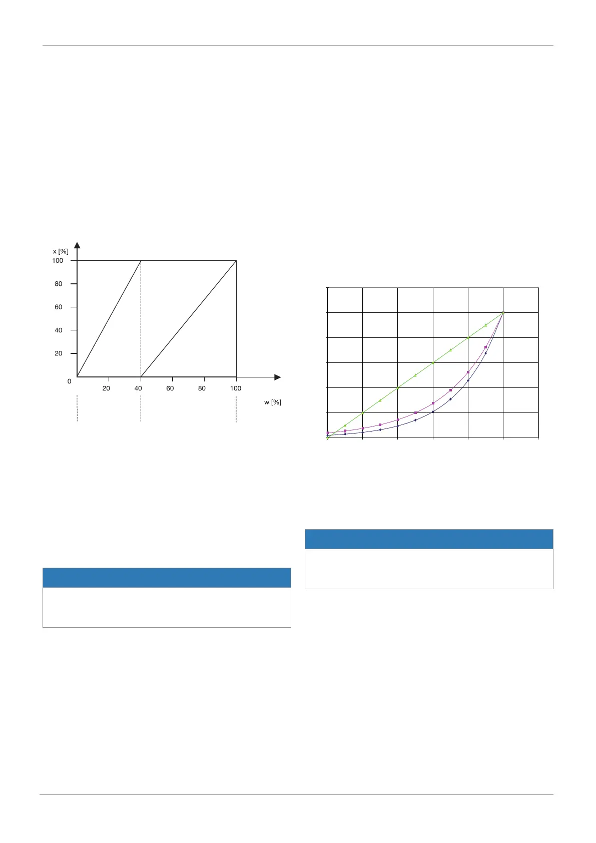
Parameters 26 and 27 in conjunction with parameter 24 serve
to limit the effective set value range. In this way split range
tasks with the curves
- rising / falling
- falling / rising
- falling / falling
- rising / rising
are resolved.
NOTICE
Difference between Split Start/End
▶ The difference between the Split Start and Split End val-
ues must be > 10%.
28: SetP Function
Set value function
With this function, non-linear valve characteristics can be "lin-
earised" and, with linear valve characteristics, any flow char-
acteristics can be reproduced.
Four valve characteristics are stored in the unit:
1. equal-percentage 1 : 25 (in CLOSED position valve remains
4% open)
2. equal-percentage 1 : 50 (in CLOSED position valve remains
2% open)
3. Linear
4. free
When free is selected at 30: a characteristic with 11 calibra-
tion points can be entered.
30: FREE 0%
.
.
.
40: FREE 100%
10,5
14,5
20,0
27,6
38,1
52,5
72,5
100,0
0
30
40
50
60
70
80
90
100
0,0
20,0
40,0
60,0
80,0
100,0
120,0
0 20 40 60 80 100 120
Linear and equal-percentage characteristics
Linear
Set value w [%]
Stroke x
[x]
At gaps of 10%, a flow characteristic value can be allocated to
the set value calibration point concerned. These points make
a traverse with 10 straight lines, which then provides a pattern
of the valve characteristic.
NOTICE
Entering set value calibration points
▶ Set value calibration points can only be entered with 28:
SetP Function = free.
42: Deadband
Positioner's dead band
The dead band shows the maximum permissible system devi-
ation between actual value and set value.
With DeadBand = AUTO, the dead band is matched to the re-
quirements of the control circuit during initialization. In the
other discrete settings, the fixed value for the dead band is
used.
16 System mode CLASSIC