www.gemu-group.com 29 / 71 GEMÜ 1435 ePos
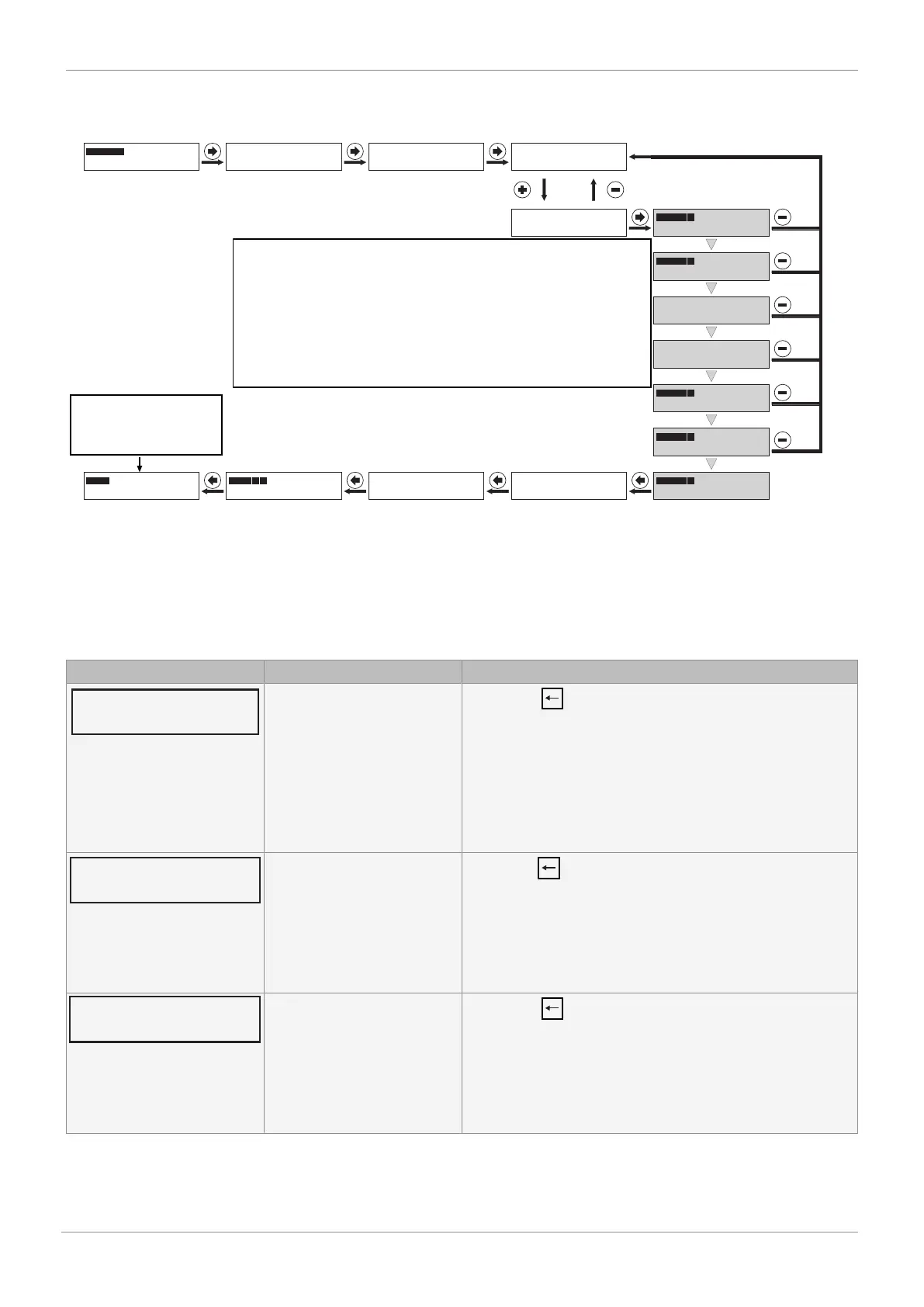
P = 45.4
D: NO INIT
Nach dem Einschalten
PRESS -> FOR 3s
C: CONFIG
länger als 3s drücken
1: SETPOINT
NO INIT
2: INIT ALL
PRESS -> FOR 3s
2: INIT ALL
P = XX.X
2: INIT RUN 1
P = XX.X
2: INIT RUN 2
up -> down
2: INIT RUN 3
down -> up
2: INIT RUN 3
P = XX.X
2: INIT RUN 4
P = XX.X
2: INIT RUN 5
INIT OK
2: INIT ALL
1: SETPOINT
PRESS -> FOR 3s
C: CONFIG
X = 55.5
B: MANUAL. W = 55.5
.. .... X = 30.5
A: AUTO. W = 30.5
länger als 3s drücken
After switching on
Press for more than 3 seconds
Press for more than 3 seconds
The valve travel times (up->down, down->up) are measured
and displayed. If these measure < 1 second, an error
is displayed and the valve travel time must be set
to at least > 1 second using the throttle screw(s). This step may need to be repeated
several times until an optimal valve travel time
can be achieved. Experience has shown that valve travel times
of approx. 1-2 seconds produce optimal control characteristics. The
two valve travel times should ideally not be
too far apart.For further information, see chapter
14.1.1 Error causes and troubleshooting during initialization
The product is
ready for operation and reacts
to the externally
specified set value.
If the message "INIT OK" appears, the product is ready for operation and can be set to the desired operating mode.
- Operating mode A: AUTO – reacts to the externally specified set value.
- Operating mode B: MANUAL – the valve position can be specified manually using the keys.
14.1.1 Error causes and troubleshooting during initialization
If an error message appears during the initialization process, proceed as described below:
Display Error cause Troubleshooting
Actuator's direction cannot be
established. Cause:
a) No compressed air supply
b) Compressed air supply too
low
c) Travel sensor wrongly con-
nected
d) Valve stroke < 3 mm
- Press the key
a) Check compressed air supply (max. 6 bar)
b) Check compressed air supply (max. 6 bar) and correct pneu-
matic connection
c) Check connection assignment
d) Check valve stroke
Zero point adjustment cannot
be carried out. Cause:
a) Incorrect travel sensor /
mounting kit
b) Adjust quarter turn travel
sensor
- Press the key
Adjust valve manually, display value P must be > 2.0 in CLOSED
position.
a) Check order no.
b) Turn quarter turn travel sensor (only on quarter turn actuat-
ors) until value P > 2.0
Zero point adjustment cannot
be carried out. Cause:
a) Incorrect travel sensor /
mounting kit
b) Adjust quarter turn travel
sensor
- Press the key
Adjust valve manually, display value P must be < 98.0 in
CLOSED position.
a) Check order no.
b) Turn quarter turn travel sensor (only on quarter turn actuat-
ors) until value P < 98.0
14 Commissioning