www.gemu-group.com20 / 71GEMÜ 1435 ePos
11 Assembly
11.3.3 Direct mounting
NOTICE
▶ Before mounting the travel sensor on the actuator, make
sure that the shaft height and the hole pattern in the actu-
ator match the dimensions of the mounting bracket 6.
1
2
3
9
10
8
7
6
5
4
Butterfly
valve
open
Butterfly valve
closed
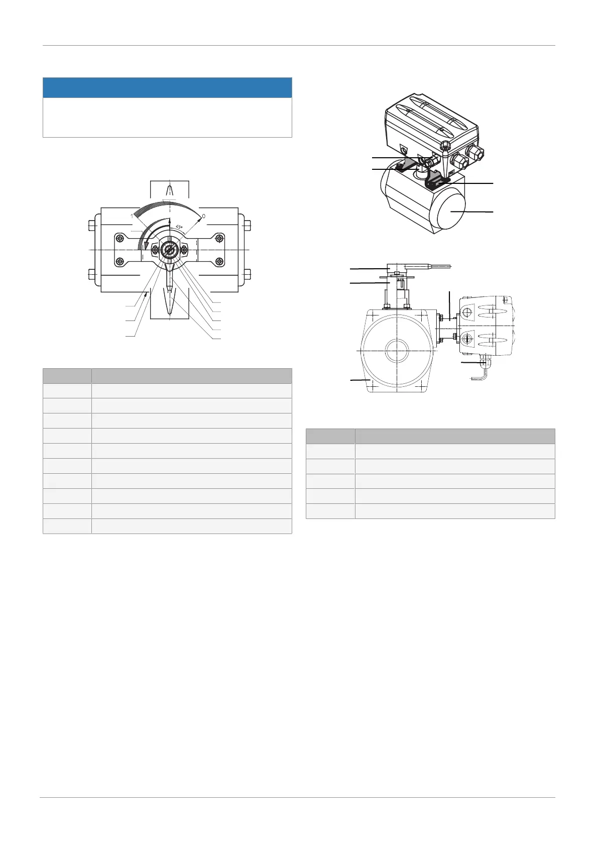
Item Name
1 Adapter marking
2 Pneumatic connection
3 Potentiometer shaft marking
4 Actuator shaft (from above)
5 Rotary potentiometer shaft
6 Adapter
7 Rotary potentiometer connection
8 Butterfly disc: Closed
9 Actuator
10 Rotary potentiometer
1. Positioner positioned above:
2. b) Positioner flanged onto NAMUR control air connectors:
Item Name
1 Mounting bracket
2 Quarter turn actuator
3 Rotary travel sensor
N NAMUR adapter
5 Cable gland