www.gemu-group.com 59 / 71 GEMÜ 1435 ePos
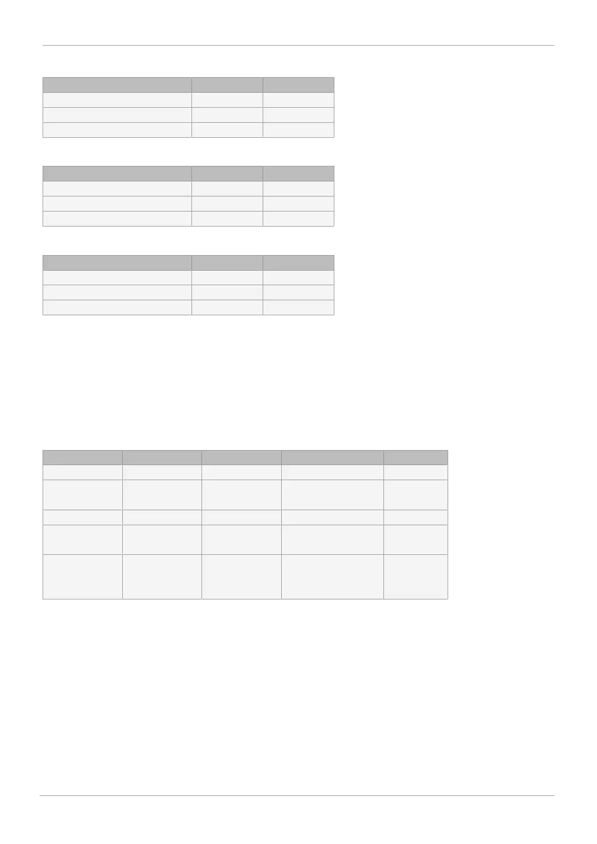
Min/Max:
Item State output A1 State output A2
x < Level Alarm1 < Level Alarm2 24 V 0 V
Level Alarm1 < x < Level Alarm2 0 V 0 V
Level Alarm1 < Level Alarm2 < x 0 V 24 V
Min/Min:
Item State output A1 State output A2
x < Level Alarm1 < Level Alarm2 24 V 24 V
Level Alarm1 < x < Level Alarm2 0 V 24 V
Level Alarm1 < Level Alarm2 < x 0 V 0 V
Max/Max:
Item State output A1 State output A2
x < Level Alarm1 < Level Alarm2 0 V 0 V
Level Alarm1 < x < Level Alarm2 24 V 0 V
Level Alarm1 < Level Alarm2 < x 24 V 24 V
Switch point for Alarm 1. When the switch point has been reached, digital output A1 (24 V DC output) is switched.
Switch point for Alarm 2. When the switch point has been reached, digital output A2 (24 V DC output) is switched.
17.2.5.2.4 Setting error output functions
Error Output:
Submenu for setting the error output.
Function of the error message output (24 V DC output).
The table shows which functions are relevant to the setting of the output at which setting value.
Setting Error Time Error Level Range Functn Mode [OFF]
Error fn X X
Error+
Inactive
X X X
Range X
Error+
Range
X X X
Error+
Range+
Inactive
X X X X
Error Time:
Monitoring time for setting the error messages (10 x travel time). The set value (s) serves as a specified value for the time
within which the positioner must have reached the idle state. The associated trigger threshold is specified with parameter 17.
When the set time has been exceeded, error message output ERR is set to 24 V DC.
Error Level:
Trigger threshold of the error message
Here, a value (%) can be set for the permissible size of system deviation for triggering the error message.
If parameters 16 and 17 are both set to AUTO, the error message is set if the slow-travel zone has not been reached within a set
time. This time is 10x (parameter value AUTO) the initialization travel time.
Range Functn:
Range monitoring of the set value signal
Here, it is possible to set whether the Range error signal is triggered when it falls below 4mA (cable break monitoring) or ex-
ceeds 20mA (short-circuit monitoring).
17 System mode ADVANCED