Genelec Loudspeaker Manager (GLM) 4 - System Operating Manual page 23 of 87
4.3 Cabling of the GLM Management network
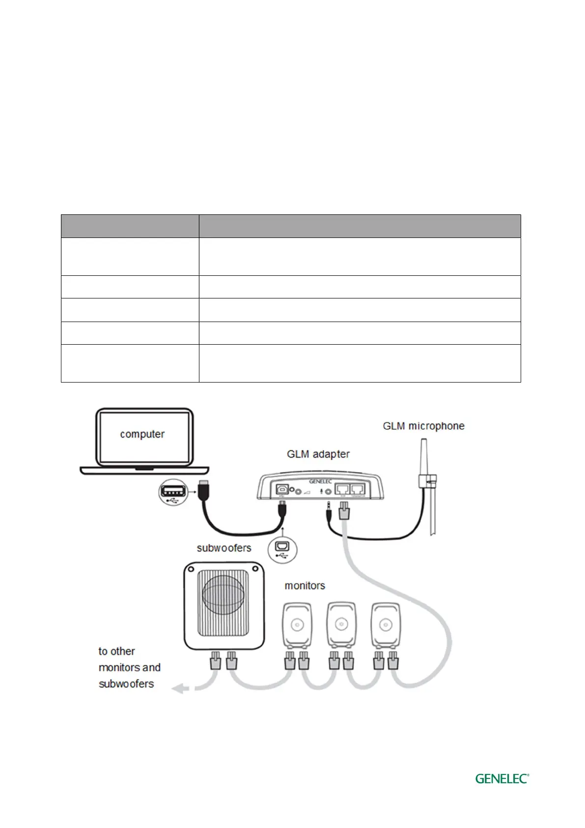
The GLM management network cabling is very easy. Connect the GLM adapter (8300-416) to the
computer USB port using the supplied USB cable, avoid using an USB -hub if possible. Connect
the GLM adapter to all SAM monitors and subwoofers in daisy-chain fashion (Figure 12) using the
network cables supplied with each monitor and subwoofer. You can connect in any order. Just be
sure to connect all monitors and subwoofers.
Table 1. Connections on the GLM adapter (from left to right)
Connector Use
USB (type B) Connects the GLM adapter to a computer USB interface or USB power
supply (stand-alone volume control)
Volume (3.5 mm jack) Connection for Genelec volume controller
Microphone (3.5 mm jack) Connection for Genelec calibration microphone
GLM Net (RJ45) GLM management network connection
Terminator (RJ45) Return termination for the GLM management network from the last
monitor, in case of network cabling being greater than 100 meters.
Figure 12. Connections of GLM management network, measurement microphone, and computer