Electrical Schematic
DPL Super Series DC Models
(before serial number DPL07-1499)
September 2016Section 6 • Schematics
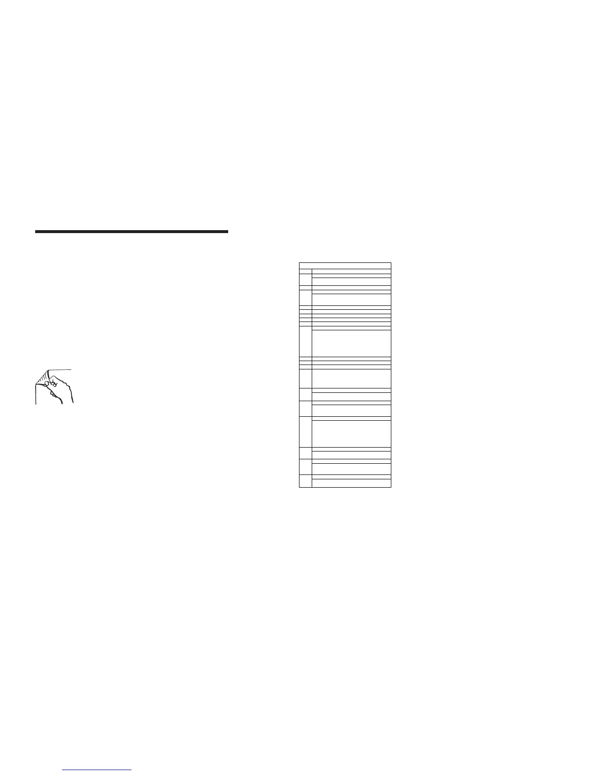
Note: Use these 2
legends for the
schematic on the
opposing page.
ABBREVIATION LEGEND
Item Description
Battery B
B2 = 12V Battery
B4 = 8 AA Batteri es
D5 Power supply AC
Enclosure EN
EN1 = Platform control box
EN2 = Ground control box
EN4 = Power to platform GFCI receptacle
F11 Fuse, 175 AMP
FB2 Warning light
GND Ground
H4 Descent alarm
KS1 Key switch ground/platform
Led or light L
L5 = Power indicator (ground)
L6 = Low ba tte ry indic ator for auxiliary (ground)
L7 = Low battery indicator — main (ground)
L12 = Outrigger — front left (ground)
L13 = Outrigger — front right (ground)
L14 = Outrigger — rear left (ground)
L15 = Outrigger — rear right ( grou nd)
M5 H ydraulic power unit
N.C. Normally closed
N.O Normally open
*N Note with description
*N17 = Na rrow platform un its:
WH and BK wires replace BL and OR wires
*N27 = Units with out plug:
WH and BK wires replace BL and BN wires
Power switch P
P1 = Emergency Stop button at ground controls
P2 = Emergency Stop button at platform controls
Quick disconnect QD
QD1 = Battery quick disconnect
QD3 = Control cable — to platform control box
QD4 = Control cable — to base
Switch SW
SW 8 = Control activate
SW11 = Platform up/down
SW12 = Auxiliary down
SW13 = Outrigger interlock — front left
SW14 = Outrigger interlock — front right
SW15 = Outrigger interlock — rear left
SW16 = Outrigger interlock — rear right
Electronic component U
U9 = Battery Charger
U10 = PC board
Wiring component W
W3 = Terminal strip — 3 pole 3 pin (U10)
W4 = Terminal strip — 14 pole 14 pin (U10)
W5 = Terminal strip — 5 pole 10 pin
Valve coil Y
Y7 = Platform down
Y30 = Normally open dump valve
 Loading...