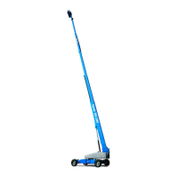
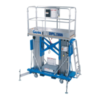
7 - 12 DPL-25S • DPL-30S • DPL-35S Super Series Part No. 40462
September 2016
Section 7 - Repair Procedures
HYDRAULIC POWER UNITS
12 The power unit should not be able to lift the
platform. If the power unit lifts the platform, turn
the relief valve clockwise or counterclockwise
until the adjustment is correct.
13 Hold the relief valve screw and tighten the lock
nut. Be sure the relief valve screw does not
turn.
14 Bleed the hydraulic system by raising the
platform to full height. If the pump cavitates or
platform fails to reach full height, add hydraulic
oil until the pump is functioning correctly. Do not
overfill the hydraulic reservoir.
Component damage hazard. Do
not continue to operate the
machine if the hydraulic pump is
cavitating.
15 Install the breather cap and the base cover.
3-6
How to Adjust the Pressure
Relief Valve
1 Remove the base cover.
2 Remove the breather cap from the reservoir.
3 Fill the reservoir up to the sight gauge with
Dexron ATF hydraulic oil equivalent.
4 Install the breather cap.
5 Follow the appropriate operator's manual to set
up the machine.
6 Place maximum rated load into the platform.
Secure the load to the platform.
Maximum capacity ANSI CE CSA
DPL-25S 750 lbs 750 lbs 600 lbs
340 kg 340 kg 272 kg
DPL-30S 750 lbs 750 lbs 600 lbs
340 kg 340 kg 272 kg
DPL-35S 600 lbs 600 lbs 500 lbs
272 kg 272 kg 227 kg
Note: Be sure to add the weight of the operator, as
part of the maximum load.
7 Hold the relief valve screw and loosen the lock
nut.
8 While activating the platform up function, turn
the relief valve screw clockwise, just until the
platform begins to raise.
9 Fully lower the platform.
10 Add an additional 30 pounds (14 kg) to the
platform. Secure the additional weight.
11 Raise the platform slightly.
 Loading...