Service Manual May 2018
Electrical Component and Wire Color Legends
116 GR
™
• QS
™
R • QS
™
W Part No. 1275811GT
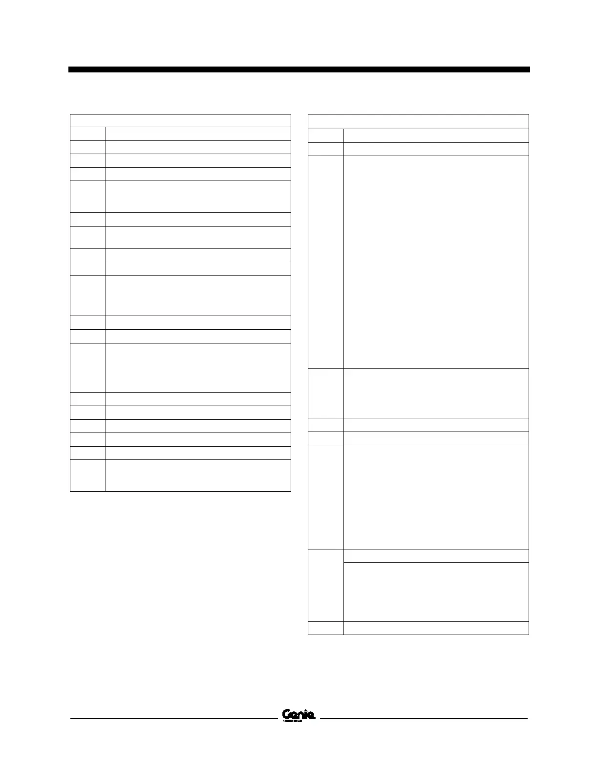
ELECTRICAL COMPONENT LEGEND
Item Description
B1 - B4 Battery, 6V DC
CB1 Circuit breaker, 7A
CON1 Contactor, Motor controller power
D Diode
D1 - Motor controller enable, 3A
D2 - Motor controller, 3A
EN1 Enclosure, AC outlet box
F Fuse
F1 = 275A
FB1 Flashing beacon
GND Ground
H Horn or Alarm
H1 = Alarm, GCON
H2 = Automotive style horn (option)
H3 = Alarm, PCON
JC1 Joystick controller
KS1 Key switch
LS Limit switch
LS6 = Platform down
LS7 = Pothole
LS8 = Pothole
LS18 = Load sense (option)
M1 Hydraulic power unit
NC Normally closed
NCHO Normally closed held open
NOHC Normally open held closed
OSP Obstruction sensing pads (QSR models)
P Red emergency stop button
P1 = At ground controls
P-2 At platform controls
ELECTRICAL COMPONENT LEGEND cont.
Item Description
QD Quick disconnect, battery pack
QD1 = Battery quick disconnect
QD3 = Control cable to ground
QD4 = Control cable to platform
QD30 = AC plug
QD31 = GCON ECM, ground and platform controls
QD32 = GCON ECM, switches and sensors
QD33 = GCON ECM, function manifold
QD34 = Power buss, switches and sensors
QD35 = Ground buss, switches and sensors
QD36 = Pothole guard switches
QD37 = Down limit switch
QD38 = Level sensor
QD39 = Ground buss, function manifold
QD40 = Drive reverse coil, Y5
QD41 = Drive forward coil, Y6
QD42 = Steer right coil, Y3
QD43 = Steer left coil, Y4
QD44 = Platform up coil, Y8
QD45 = Obstruction pads, power signal in
QD46 = Obstruction pads, power signal out
QD47 = Platform controls PCB, power/signal in
QD48 = Platform controls PCB, E-Stop and alarm
QD49 = Platform controls PCB, joystick
R Resistor
R1 = 1k Ohm, 2W
R2 = 200 Ohm, 10W
R27 = 25 Ohm, 2W
R30 = 200 Ohm, 10W
S7 Level sensor
U Electronic Component
U1 = Electronic Control Module, GCON
U2 = Printed Circuit Board, PCON
U4 = AC/DC Inverter (option)
U6 = Motor Controller
U9 = Battery Charger
U47A = Obstruction sensing pad (hydraulic tank
side)
U47B = Obstruction sensing pad (battery tray)
U47C = Obstruction sensing pad (steer end)
U47D = Obstruction sensing pad (ground control
side)
Y Valve Coil
Y3 = Steer right
Y4 = Steer left
Y5 = Drive reverse
Y6 = Drive forward
Y7 = Platform Down
Y8 = Platform Up
Z1 Zener diode
 Loading...