Comander Perimeter Security System
Engineering and Installation Manual
Page 29 of 72
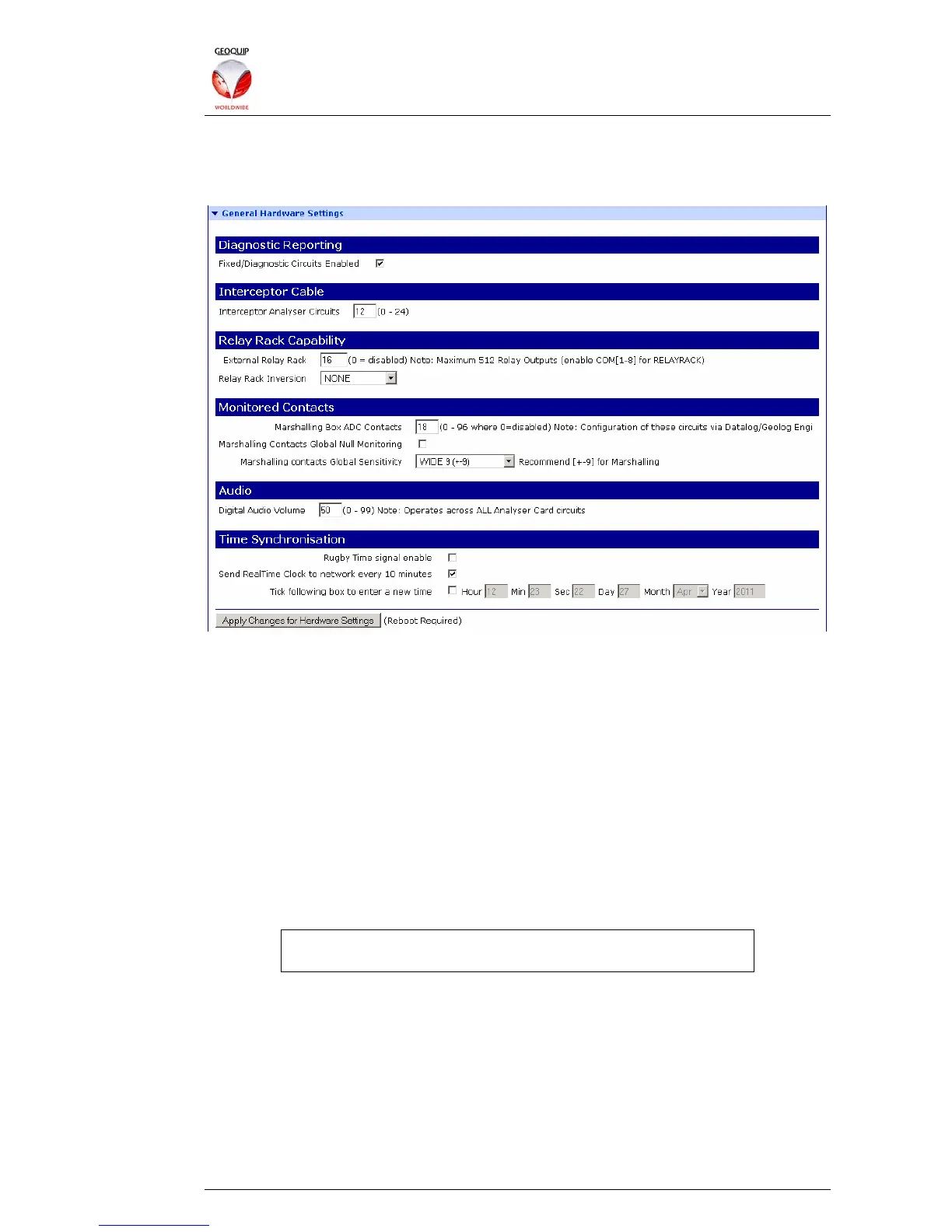
2.5.4 General Hardware Settings
This section of the Configurator contains global options for the Rack connections and
circuit enumeration.
2.5.4.1 Diagnostic Reporting
The Fixed/Diagnostic Circuits Enabled check-box is used to make the Comander unit
report some local diagnostics to the Collator or SMS as "fixed" circuits. If selected, the
diagnostic circuits are appended at the end of the normal list of circuits which are
annunciated to the SMS.
A full list of the Fixed Circuits is provided on the Configurator's View Auto-SMS page,
as described in section 2.4.6 above.
2.5.4.2 Interceptor Cable
The Interceptor Analyser Circuits option must be set to the number of Interceptor
cables which are used by the system, and is the number which will be annunciated to
the SMS. Interceptor circuit connections must be made in the Marshalling box starting
at connector 01, and going sequentially up to this total.
It is not possible to configure Comander to use non-contiguous
connections in the Marshalling box.
2.5.4.3 Relay Rack Capability
The External Relay Rack option must be set to the total number of Relay Rack relays
controlled by the Comander. Only one COM port is normally used to connect Relay
Racks, but up to four Relay Racks can be daisy-chained onto this connection, allowing
up to 512 relays in total.
The Relay Rack Inversion option can be used to change some or all of the relays from
the default setting of Normally Closed to Normally Open. A setting of NONE leaves all
relays normally closed, while a setting of ALL CARDS makes all relays normally open.
You can also choose to invert only the relays attached to even-numbered or odd-