Comander Perimeter Security System
Engineering and Installation Manual
Page 33 of 72
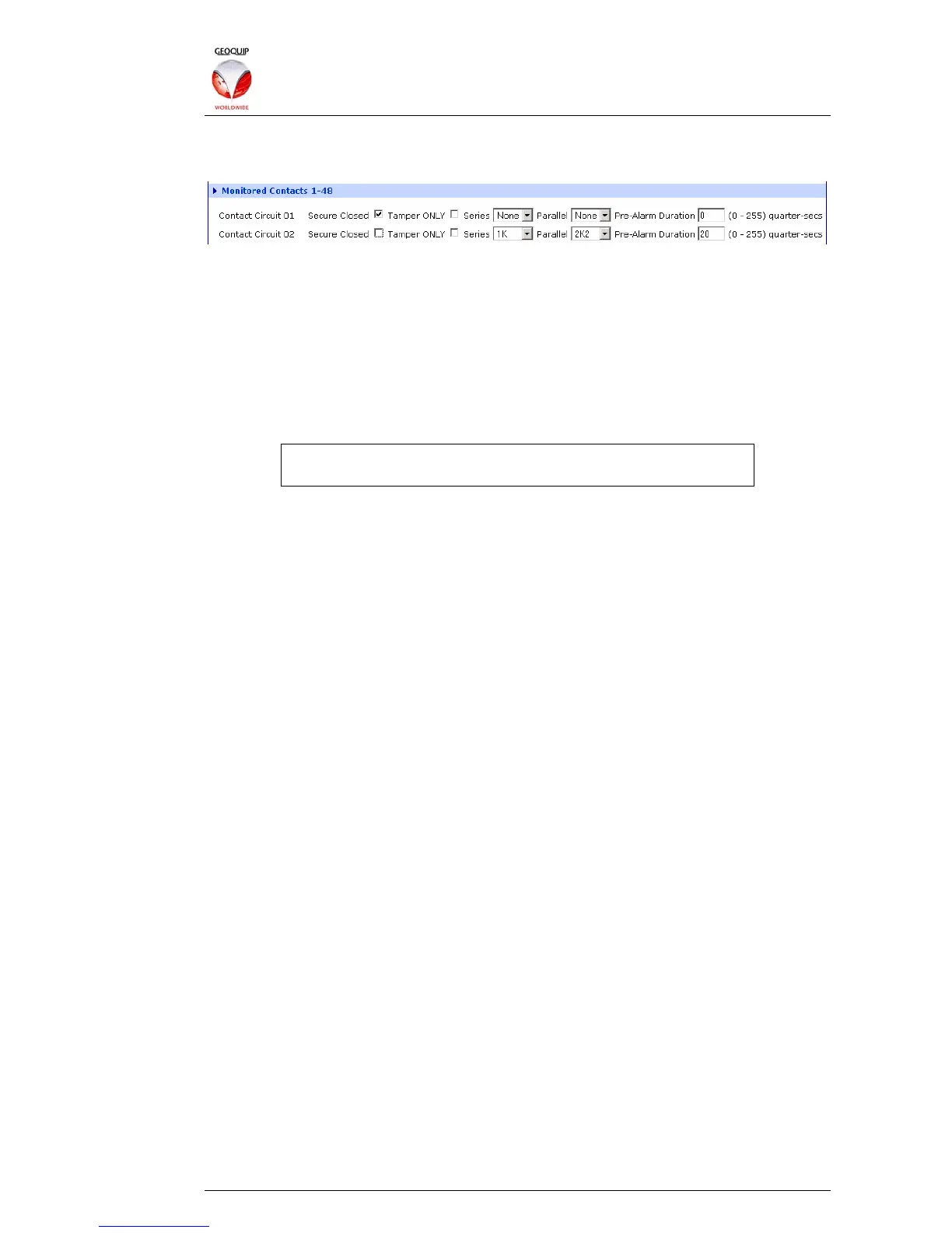
The resistor value settings, and other options, can be configured individually for each
Monitored Contact circuit:
2.5.6.2 Secure Closed
This setting allows the use of systems which use both Open and Closed contacts to
indicate a secure circuit. Un-check the box for circuits which use open switches or
relays to indicate a secure state.
2.5.6.3 Tamper Only
If the circuit is set to Tamper Only, it does not generate an Alarm condition when
triggered, but a Tamper condition.
Note that if this option is selected, the Pre-Alarm Duration option
has no effect.
2.5.6.4 Setting Resistor Values
The values of the serial and parallel resistors, as shown in the diagram above, should
be entered here.
Resistor values are normally imported into the SMS when it first connects to
Comander, and can then be changed using configuration pages in the SMS program.
If you change a resistor value using the SMS, this change will be automatically
propagated to Comander, and stored as an update to its configuration.
2.5.6.5 Pre-Alarm Duration
Some types of Contact circuit suffer occasional transient activity which does not
indicate a real alarm condition. The Pre-Alarm Duration setting allows for a minimum
activation period to be set, so that activation of the contact generates only a Pre-Alarm
condition until the Delay period is exceeded. If the contacts remain active for longer
than the Delay period, an alarm condition will be triggered as normal.
The Delay period is set between 0 and 255 where 1=0.25 seconds, and each digit
represents a quarter-second. This means that the range of actual duration times is 0-
64 seconds.
2.5.7 SMS Collator
The SMS Collator function enables a Comander on the system to act as the central
target and collator for a number of annunciating devices and outputs on the network.
In some systems this role is undertaken by the SMS, but there are some situations
where it is more efficient to have one or more Comander Racks act as Collators, and
the Racks then pass the circuit information to the SMS.
When the Collator feature is used, the collating Comander Rack concatenates all the
circuits in the system into one contiguous block. This single set of circuits can then be
programmed to produce automatic output responses using the Auto-SMS feature (see
section 2.4.6 above), or annunciated to an SMS.
The order in which the devices are listed in the Collator is the order in which their
circuits appear when annunciated to the SMS.