Comander Perimeter Security System
Engineering and Installation Manual
Page 32 of 72
2.5.5.3 Pre-Alarm Settings
The Pre-Alarm system on Interceptor circuits works separately from the three channels
A, B and C, and is not analysed to detect any particular type of activity – instead the
Comander's analyser uses the overall level of the incoming audio signal to generate a
Pre-Alarm condition. To enable Pre-Alarms on a Defensor circuit, check the box
labelled Pre-Alarm.
The Level setting allows you to set the activity level at which the circuit will generate a
Pre-Alarm condition when Pre-Alarms are enabled. The Pre-Alarm Level can be set to
any value between 0 and 99.
2.5.5.4 Audio
Interceptor cable acts as a microphone, and the sound it is detecting can be monitored
in the control room. By enabling the audio and turning up the volume, the operator can
hear the actual sound which is being picked up by the cable. The sound can be
monitored at any time, whether or not the circuit is in an alarm condition.
2.5.6 Configuring Monitored Contact Circuits
2.5.6.1 What is a Monitored Contact Circuit?
A Monitored Contact is a relatively simple device comprising a pair of terminals which
are connected via two resistors to a switch or relay in a sensing device – this might be
a panic button or other manually-operated device, a magnetic switch or relay which
monitors the position of a gate, or a signal output provided by a security beam device
like Geoquip's RadioVisor, or an underground detector such as RAFID.
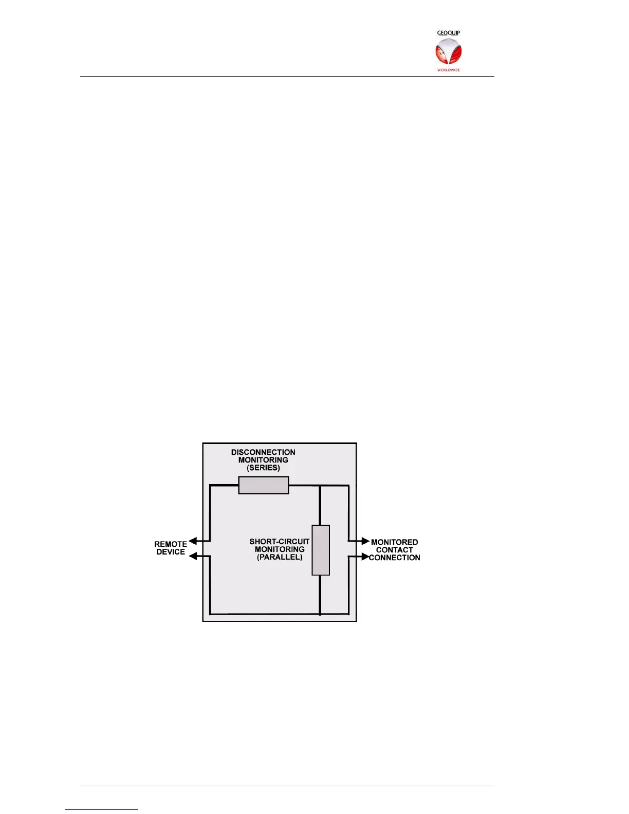
The contacts are connected in the following way:
This architecture allows Comander to monitor not just whether the remote device has
been activated (eg the panic button has been pushed), but also whether it has been
disconnected, or whether its connections have been short-circuited to prevent it from
working properly. If Comander detects that the contacts are no longer connected
correctly, it will generate a Tamper/Failure condition on the circuit. In order for this
monitoring to work correctly, Comander must be configured with the resistor values
used in the circuit.