Comander Perimeter Security System
Engineering and Installation Manual
Page 38 of 72
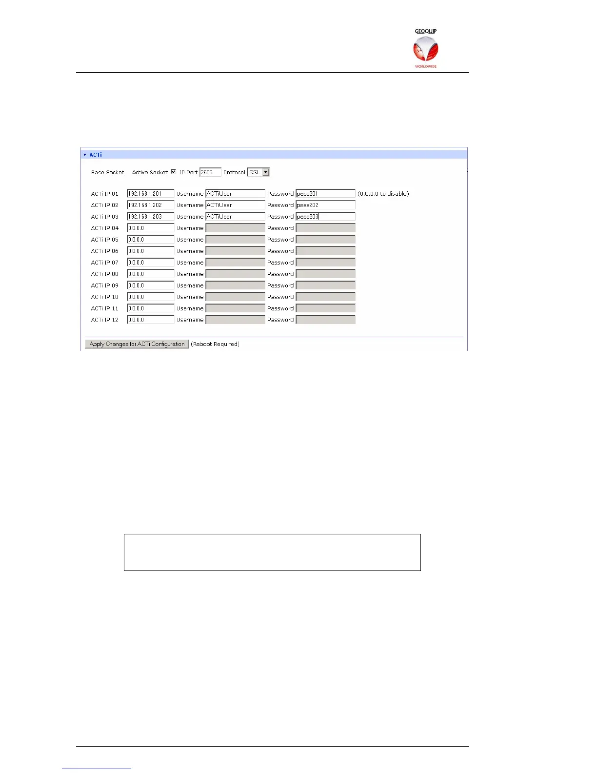
Once the CCTV matrix is connected and configured, the Active Socket option in the
ACTi section of the Comander Configurator is used to enable routing of the Matrix
control signals to the ACTi encoders which control individual cameras. The Active
Socket must be configured to use the same port number and protocol as the COM port
to which the Matrix is connected:
Up to 12 ACTi devices can be connected to a Comander via Ethernet, by allocating IP
addresses within the Comander subnet to the ACTi devices. As well as an IP address,
each ACTi device also requires a username and password, which must be entered into
the Configurator setup for that device.
If more than 12 ACTi encoders are required, more Comanders must be used. The
RS485 control bus can be extended using additional RS232 convertors, which are
connected to a serial port on a additional Comanders. Each Comander is then
configured with the IP addresses and authentication details of the devices which it is
controlling.
2.5.11 Network Topology
This section of the Configurator is used to configure the IP Addresses which are
scanned by the Comander using the Rapid Spanning Tree Protocol. An example of
how to use the RSTP/Topology feature is given in section 1.8.2.3 above.
The RSTP Scanning feature must be enabled on ONE Comander
in any system which uses a Ring, and should NOT be enabled on
ANY units in a non-Ring configuration.
RSTP Scanning Enable – this option sets the local Comander Rack to act as the
RSTP Scanner for the Ring. If any breaks occur in the Ring, the Rack's Network Ring
Topology fixed circuit will go into Tamper mode.
Send UDP Network Topology Broadcast – with this option enabled, breaks in the
Ring are not only annunciated as a Tamper condition in the Network Ring Topology
fixed circuit, but are also broadcast as a UDP data packet on the port designated in the
adjoining box. If the Extended Information option is also enabled, the UDP broadcast
will include information about the location of the break, as deduced from the sequence
of connected IP addresses in the Network Topology IP List below.
Network Topology IP List – this allows you to enter up to 64 device IP addresses, in
the order in which those devices are attached to the Ring. By checking which devices
are accessible, and via which routes, the RSTP scanning system can deduce
information about the likely location of any breaks it detects.