Comander Perimeter Security System
Engineering and Installation Manual
Page 39 of 72
The Comander's IP Address and Subnet Mask setting (in the
Configurator Network Settings page) must be configured so that
it can communicate with all the devices listed in the IP List.
2.5.11.1 Notes on Enabling and Disabling RSTP Scanning
The process of enabling or disabling scanning on a working Rack or Ring should be
undertaken with great care. If scanning stops while the Ring is intact, this will result in
a broadcast storm which will render the system inoperable until the Ring is broken, or
the scanning is restored. The system may take some time to return to normal after a
broadcast storm has occurred. Likewise, scanning should not be enabled on more
than one Rack in a Ring simultaneously.
Say for example that you have a fibre Ring system with several Comander Racks, and
you want to transfer the RSTP scanning role for the system from the original Rack
("Rack A") to a different one ("Rack B"). The process should be undertaken in the
following sequence:
• In Rack B's Configuration, create the Network Topology IP List – this may be
similar to the list used in Rack A, but is likely to differ slightly depending on the
relative positions of the two Racks in the Ring;
• Break the Ring by disconnecting one of the fibre connections on Rack A;
• In Rack A's Configurator, on the Network Topology page, disable RSTP
scanning by un-ticking the RSTP Scanning option, then click the Apply button
below and reboot (you can also delete Rack A's IP address list at this point if
you wish);
• In Rack B's Configurator, on the Network Topology page, enable RSTP
scanning by ticking the RSTP Scanning option and Applying then rebooting;
• Reconnect the Ring by reconnecting the fibre connector on Rack A.
This sequence ensures that there are never two Racks trying to operate RSTP
scanning at the same time, and that scanning is always enabled whenever the Ring is
intact. This should ensure correct networking behaviour and avoid broadcast storms.
2.5.11.2 Systems with Multiple Rings
It is possible to set up Comander networks with separate, segmented Rings. In this
situation, it may be appropriate to enable RSTP scanning for each Ring separately, on
different Comanders. A full description of such a system is beyond the scope of this
manual – please contact Geoquip Technical Support for guidance on setting up this
type of Comander architecture.
2.5.12 Digitised Audio Feature
When an Interceptor circuit goes into Alarm mode, the SMS can issue a command to
switch on the audio for that circuit. Because Interceptor cable is microphonic,
operators can "listen" to what is happening in the vicinity of the cable by monitoring the
audio signal it is generating – this is illustrated in the example in section 1.8.2 above by
the presence of an audio amplifier and speaker connected to the Control Room rack.
Once switched on, the analogue audio signal captured by the
Interceptor cable is digitised, and broadcast across the network as
a PCM UDP data stream on port 10001. If more than one
Interceptor is "switched on" in this way, the broadcast is a mix of
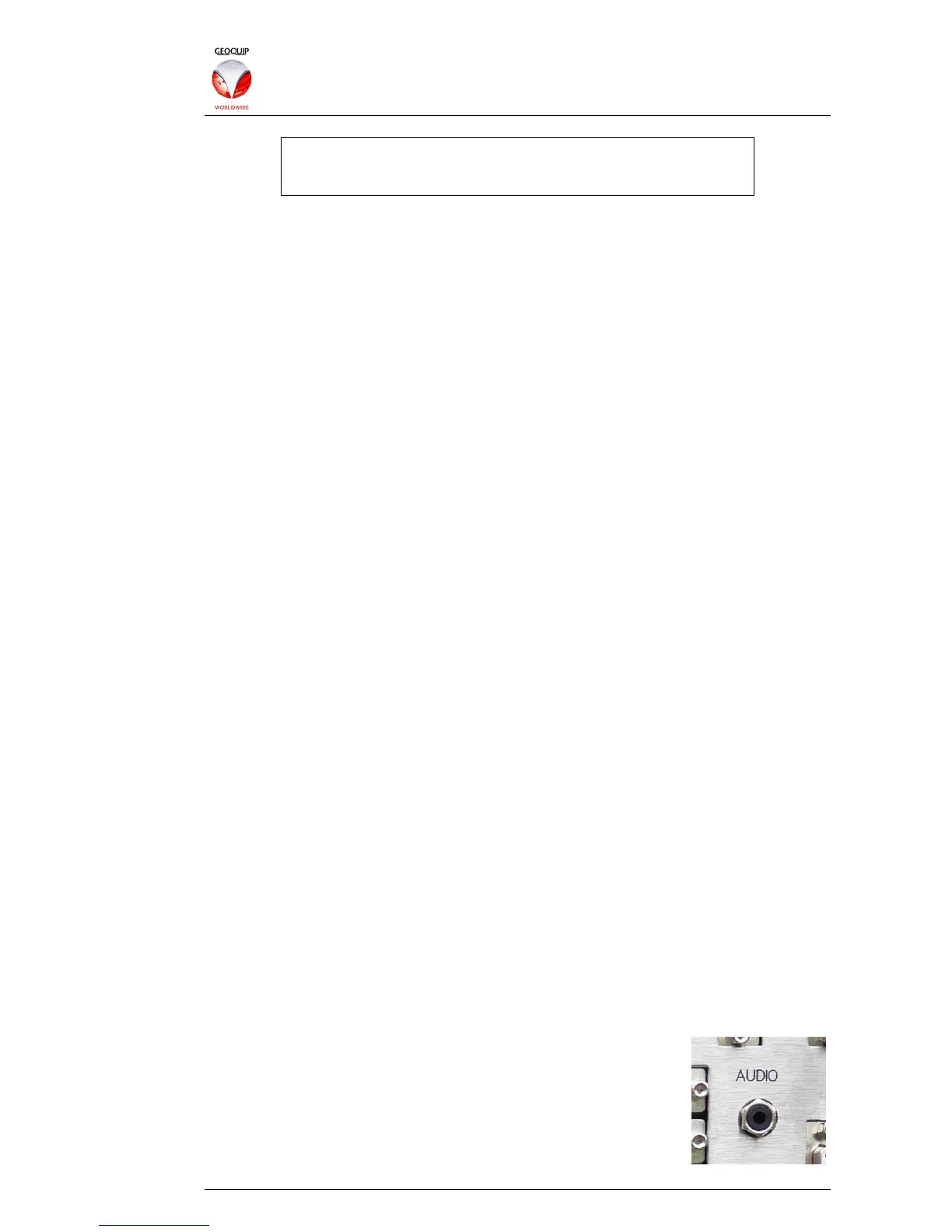
all the audio data. Each Comander can output the audio
broadcast as a line-level analogue signal via the Audio connector
on the rear panel. This connector is a mono 3.5mm jack socket.