14 SmartFan EN
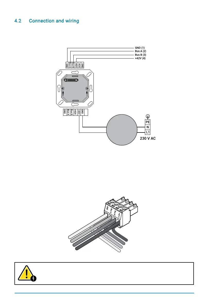
4.2 Connection and wiring
Allelectricalworkmustbeperformedbyaqualiedelectrician.Makesurethatallwiring
is done correctly.
When connecting the control unit to the SmartFan unit, a 4-pin 3.50 mm connector plug
must be mounted on the cable. The connector must be wired as shown below. When
connecting the plug to the fan unit holder, the screws should point downwards. When
continuing the cable to a further SmartFan unit, the colours of the input and output wires
in the selected plug openings must match each other.
INCORRECT WIRING CAN CAUSE DAMAGE TO THE FAN UNIT.
Black
Red
Power
supply
unit
Port row 1
Port row 2
TOP
GND (1)
Bus A (2)
Bus B (3)
+42 V (4)
+42 V (4)
Bus B (3)
Bus A (2)
GND (1)
Incoming cables
Outgoing cables
(next SmartFan)