Page 27
SAFETY DEVICES
Input for safety devices
X2
The control recognizes and works with 3 dierent safety edges.
Alternatively, a light curtain can be connected.
Each one needs a special 4 core spiral cable and includes an optional shutter pass - door or
slack wire switch contact.
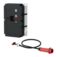
The spiral cable connection must be made on the print with the plug provided. The opposite
side of the cable is connected to a terminal box or a signal (pressure switch) emitter.
Door safety switch X2
This switch could be tted on to the surface of the door and will be connected with the spiral
cable into the control panel. This door safety switch can used and programmed in two functions.
Menu item 3.4 a change of function can be realised.
Function Reaction following the activation
Slake rope / Contact interrupted: No reaction door stops
Pass door
Contact closed: Door ready to run.
Crash detector Contact interrupted: Door will stop immediately out of the movement.
Contact closed: Switches the door function into Hold-to-run Mode.
(If a GfA frequency inverter drive would be in use,
the function changes to very slow speed). A reset
is available and made when pushing the built-in
STOP-button for a minimum of three seconds.
Important note!
Connect safety edge systems in accordance with EN 12978.
"Hold-to-run" door operating mode can always be used should the safety edge
be defective.
Electrical safety edge
The input is meant for an electrical safety edge (NO) with a terminal resistance of 8k2
(+/-5 % and 0,25 W).
If there is a short circuit, fault indication F2.4 is displayed.
If there is an open circuit, the F2.5 fault indication appears.
Pneumatic safety edge
The input is meant for a pressure wave switch system (NC) with a terminal resistance of 1k2
(+/-5 % and 0,25 W). Upon activation or permanent disconnection of the current circuit, the
F2.6 fault indication appears.
If there is a short circuit, fault indication F2.7 is displayed.
The pressure wave switch system needs to be tested with CLOSE nal limit position. The
test phase is initiated automatically by the pre-limit for DES. If no switching signal is gene-
rated on the pressure wave switch within 2 seconds, the test is negative and the fault indi-
cation F2.8 is displayed.