Page 8
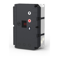
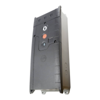
ENCLOSURE INSTALLATION
Before mounting the enclosure, the surface has to be checked for atness, slope and freedom
from vibrations. Mounting must be vertical. It is important that the door can be clearly seen
from the position of the control through-out its travel.
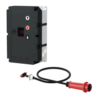
CONNECTING THE CONTROL AND THE ELEKTROMATEN
®
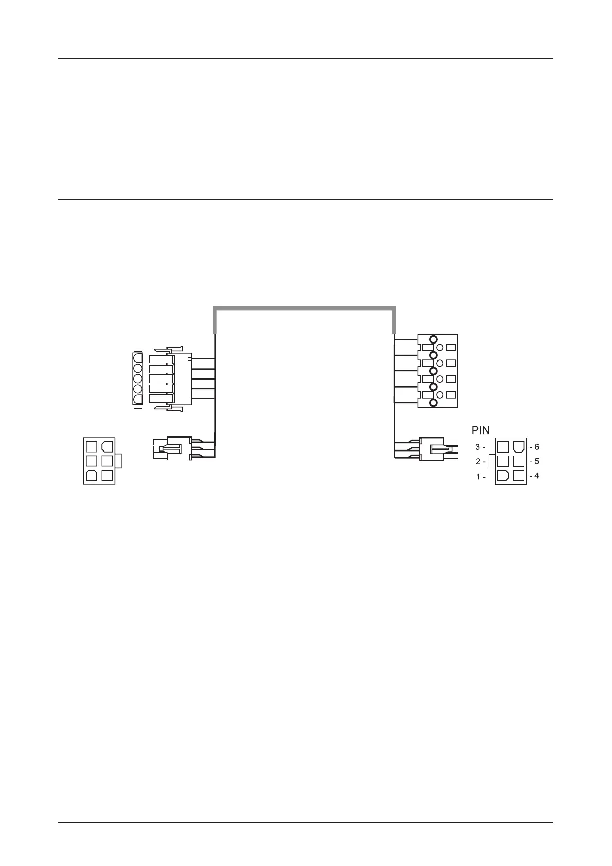
After the drive and control are tted they can be connected with a plug-in cable. The cable
has plugs on each end and for easy tting. The plugs for motor and control panel are dierent
and cannot be interchanged.
Connection cable for
digital limit (DES)
Control panel TS 981 ELEKTROMAT
®
Cable identication
Motor plug to control unit
PIN - Wire-No. Excution:
1 - 3 Phase W
2 - 2 Phase V
3 - 1 Phase U
4 - 4 Neutral (N)
5 - PE Earth
Limit plug-in to control panel TS 981 (DES)
PIN - Wire-No. Excution:
1 - 5 Safety chain 24 V DC
2 - 6 RS485 B
3 - 7 GND
4 - 8 RS485 A
5 - 9 Safety chain
6 - 10 8 V DC
Motor plug-in
Motorconnection (MOT)
1
2
PE
3
4
U
V
PE
W
N
3
2
1
4
PE
- 14 -
5 -
6 -
- 2
- 3
PIN