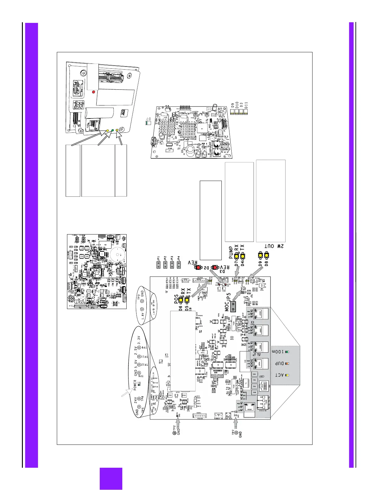
Yellow
= ON
Ethernet
Activity
Orange
= ON
Operating
in Full
Duplex
Green
= ON
Operating
at 100 mbs
D5 Yellow two-wire : Blinks during POS TX POS TX
data transmit from to D-Box.
AFP
D6 Yellow two-wire : Blinks during POS RX POS RX
data receipt to from D-Box. This is solid AFP LED
when the current loop from the D-Box is “open”.
D4 Pump Yellow Pump loop two-wire : Blinks TX TX
during data transmit from pump through to AFP
D-Box.
D7 Pump Yellow Pump loop two-wire : Blinks RX RX
when data is sent to from D-Box. This is AFP LED
solid when the current loop from the D-Box is “open”.
D8 Pump Yellow Pump link two-wire : Blinks RX TX
when data is sent to pump board from the D-Box
through the . This is solid when the current AFP LED
loop from the pump board is “open”.
D9 Pump Link Yellow Pump link two-wire : Blinks RX RX
when data is sent from the pump board to the .AFP
ETH Yellow On Network connected
Off Network disconnected
Off/On No communication
Status Green Slow Blinking LED
Display connected and UPM
activated.
Fast Blinking 150 milliseconds on
150 milliseconds off) Activation
needed (display disconnected or
UPM dismounted)
TX RX/ Serial Yellow Blinking Card
reader serial port activity on or TX
RX.
Tamper Alert Red
Off No alarm
On Alarm
D2 Loop Reversed = 2 wire from RED ON CRIND
the is reversed.POS
D3 Loop Reversed = 2 wire from the RED ON PUMP
POS is reversed.
Ethernet speed
Ethernet link
good
= StatusCPU
D1 Power Green Power “good” LED:
Lights when power is applied to the AFP and the 5 V, 3.3 V,
and 2.5 V are within specifications.
Note: This diagram shows an installation with AFP without Applause Media System. For DCM2,
Applause Media System, or intercom details, see “DCM2 Board (M14576A001)”
on page 20, “DCM2.2 Assembly” on page 26, and “M09751A002 Intercom Option” on page 50.
 Loading...