MDE-5222F
18
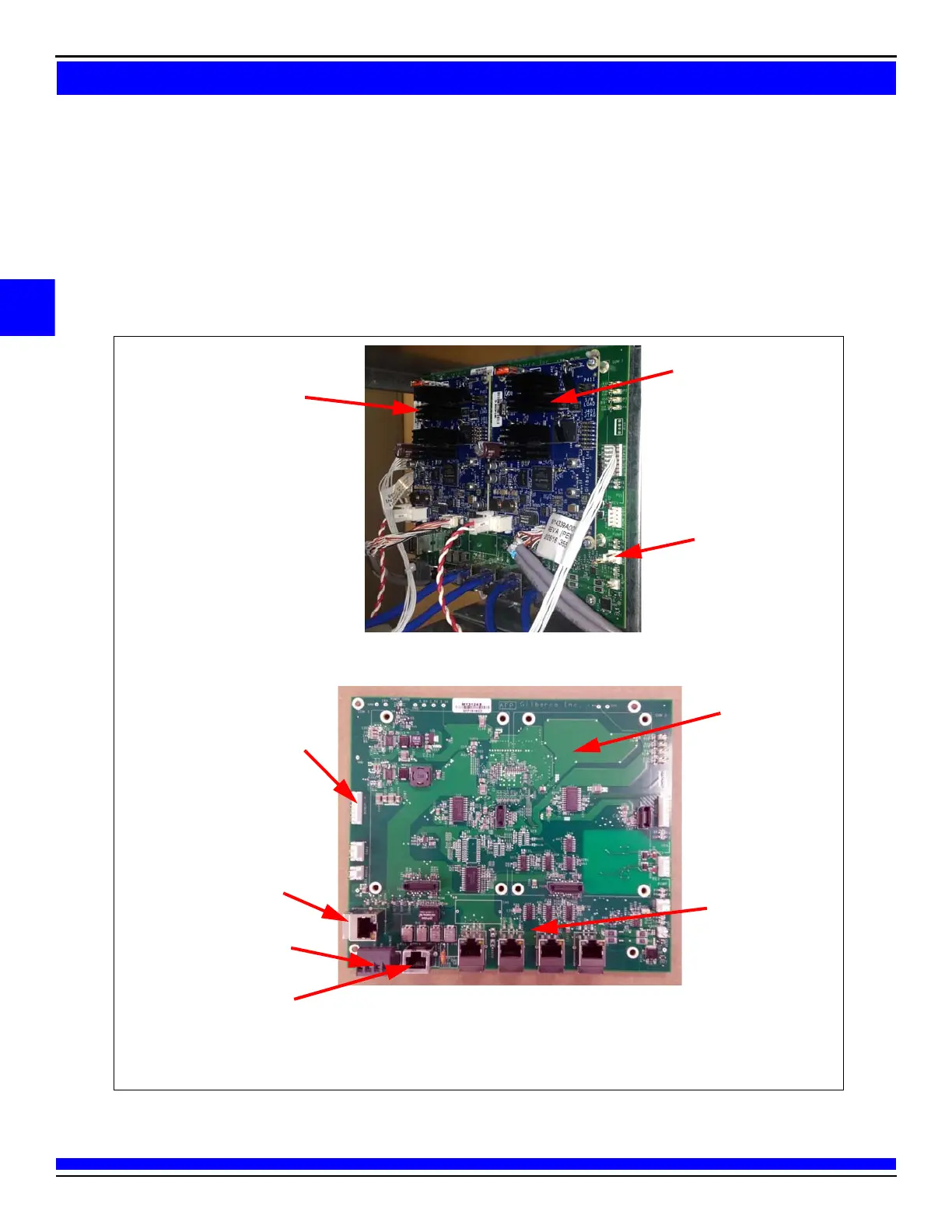
AFP (M13836AXXX)/DCM2 (M14961AXXX) Assembly
To install the AFP/DCM2 assembly:
1 Mount the AFP/DCM2 assembly on the T-rail using the thr
ee 7-mm nuts as shown in Figure 2.
Note: After installing the AFP/DCM2 assembly, ensure that no components hit the AFP/DCM2 assembly
when the door is closed. Close the door carefully to check this.
Figure 2: Installing AFP Assembly
AFP with Two GSoMs
Note: The AFP assembly optionally contains an auxiliary power supply to provide 24 V to the FlexPay IV CRIND system. It also
may contain a fuse board.
GSoM Side B (Applause
Media System Only)
GSoM Side A (Applause
Media System Only)
AFP Assembly
AFP (Front View)
AFP
Two Connections to
Side A Doors and Two
Connections to
Side B Doors
Dedicated for Applause Media
System Connection (Discrete
Wire)
P302 A is Installed on the Same
Side as the Calibration Switch
Direct Ethernet from
Back Room
Spare Ethernet
®
Connection
(For example, for Service
Laptop Port)
(i)
(ii)
DCM2 layout is similar to AFP layout
 Loading...