MDE-5222F
20
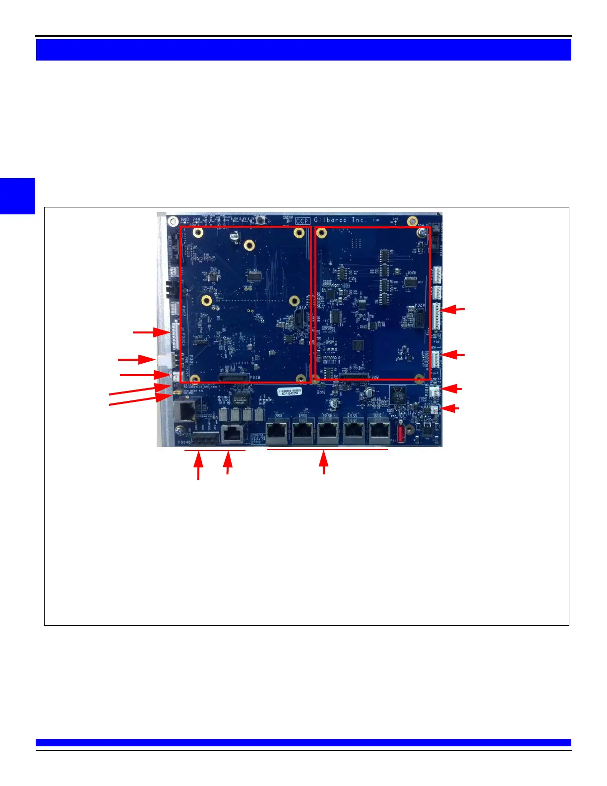
DCM2 Board (M14576A001)
The DCM2 board mounts in the same location as the M13124A001 AFP, with the same cable connections.
DCM2 board provides the same functionality as the AFP and also provides a high-speed data connection for
Applause Media System, Insite360 Encore, and EMV applications, if required. It can also host two GSoM
boards for Applause Media System, and on the rear side there is a mount-point for the SSoM for Insite360
Encore.
Figure 4: DCM2 Board (M14576A001)
GSoM A
GSoM B
P302A to Side B Door
Pump and CRIND Two-wire
Field Connections
(see Note 2)
P302A to Side A Door
24 V In
24 V Out
J3
J4
Out=Generic
In=MOC
(see Note 1)
Two-wire connection Out to
Pump (required for Applause
Media System)
P304B Convenient
Ethernet Field Wiring
Wired in Parallel With
J304A (use one only).
RJ-45 for Dispenser
Connections
P304A RJ-45 Field Wiring Point
24 V Out
Notes: 1) If J3 is ON, P300 is used for POS, Applause, and Insite360 communication.
2) If J3 is OFF, P300 is disabled and P304 is used for POS, Applause, and Insite360 communication (CAT5 or DCM connections).
 Loading...