Gill Instruments Ltd
_____________________________________________________________________________________________________________
________________________________________________________________________________________________
WindObserver II Page 11 Issue 18
Doc. No. 1390-PS-0004 January 2009
6.2. Bench system test
Note: Prior to physically mounting the WindObserver II in its final location, we strongly
recommend that a bench system test be carried out to confirm the system is configured
correctly, is fully functional and electrically compatible with the selected host system and
cabling (preferably utilising the final cable length). The required data format, units,
output rate, and other options should also all be configured at this stage. If an Integrity
Check Chamber (ICC) has been purchased refer to Section 10.6.
6.3. Cabling
Cable type
A RS422 compatible cable should be used, with the number of twisted pairs matching the
application. If both the (optional) Heating and Analogue outputs are utilised, then a 9 pair
cable is required.
Generic description – Twisted pairs with drain wire, screened with aluminised tape,
with an overall PVC sheath. Wire size 7/0.2mm (24 AWG)
The table shows some suitable manufacturers’ references; other manufacture’s equivalents
can be used.
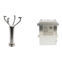
Table 1
No. of pairs Gill ref.
Belden
ref.
Batt electronics
ref.
2 - 9729 -
3 026-02660 9730 91030
4 026-03156 9728 91199
9 026-02663 8774 91009
Cable length
The typical maximum length at 9600 baud is 1km (3200ft), using the recommended cable.
If any problems of data corruption are experienced (due to, for example, a high local
electrical ‘noise’ level), then a lower baud rate should be used. Alternatively, a thicker or
higher specification cable can be tried. See also Section 6.1
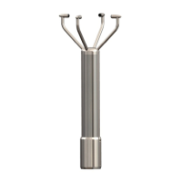
Cabling and junction box
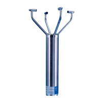
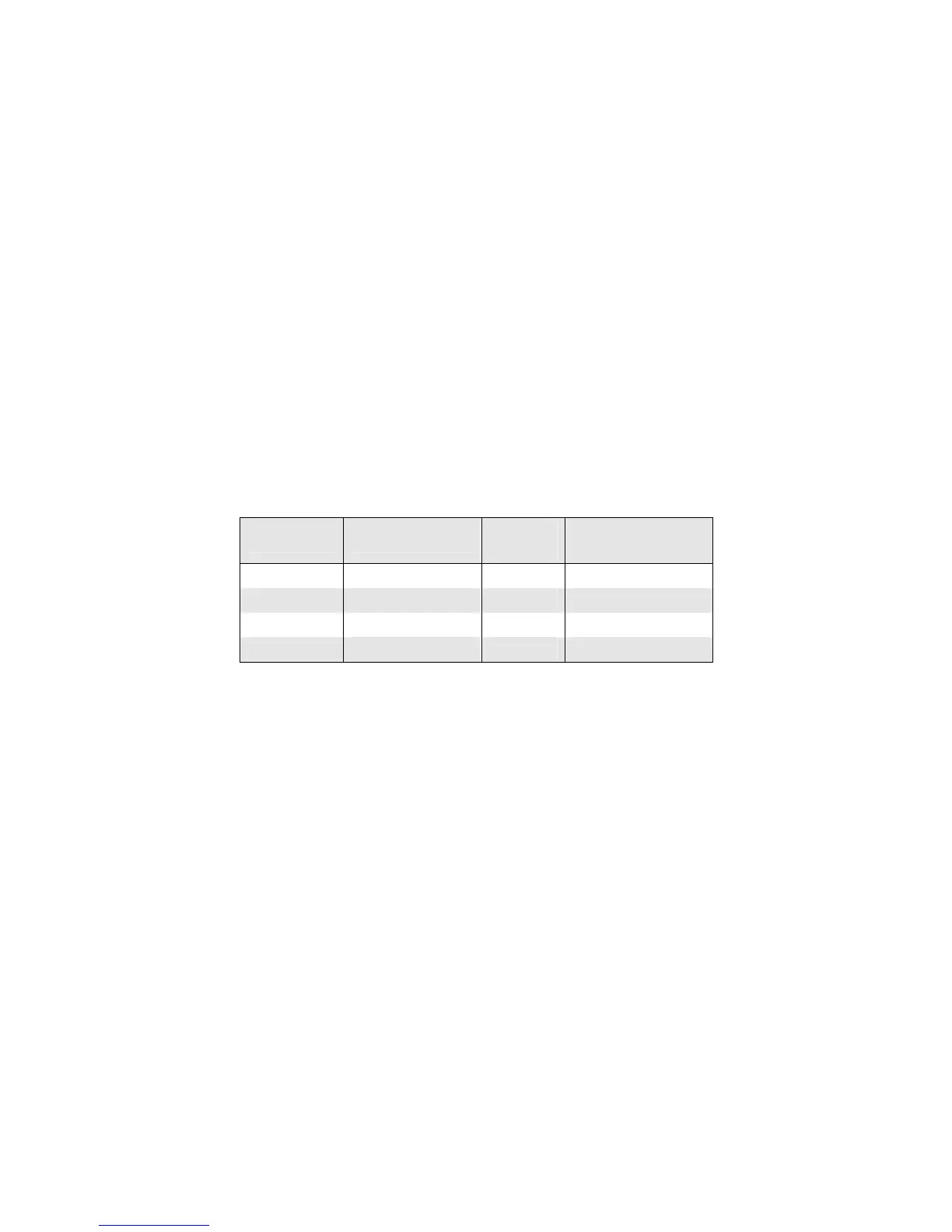
The WindObserver II unit is fitted with a flying 9 pair cable attached (2m or 10m long).
This must be terminated in a suitable terminal box to IP66 or better, fitted with glands to
prevent moisture ingress.
The cable type from the terminal box to the host system must be as specified above. If any
cable is likely to be exposed to mechanical damage, it must be enclosed in a suitable
conduit or cable tray. The cable must be securely fixed with cable clamps or equivalent,
such that the cable is not under stress at the cable glands.
The gland area at the base of the WindObserver II should not be directly exposed to
moisture, as whilst the gland is sealed when mated, the anemometer is vented to air at the
base to avoid pressure build up. If an IP66 rating is essential or the unit is mounted other
than ‘right way up’ use the gasket provided in the mounting kit.