Gill Instruments Ltd
_____________________________________________________________________________________________________________
________________________________________________________________________________________________
WindObserver II Page 28 Issue 18
Doc. No. 1390-PS-0004 January 2009
8.3. Networking
Gill Proprietary Network
Each anemometer connected to the network MUST be given a unique Unit Identifier
(Letters A to Z), and set to a polled tri-state mode (UV or Polar) (M3, M4 or M13).
In these modes the communications transmit line is tri-state unless the anemometer is
responding to a command. If used in a multi drop system then it is recommended that Unit
Identifiers A, B, C, D, E, F, K, M, N and P are not used.
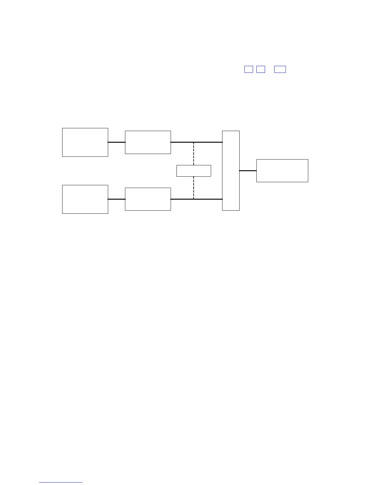
Configuring WindObserver II for Half Duplex Operation.
1) Set up Two Terminals: One for RS485 Half Duplex and the other for RS422 Full
Duplex.
SWITCH WObsII
RS485 I/F
(USB)
RS422 I/F
(USB)
HYPER-TERMINAL
A (Half-D)
HYPER-TERMINAL
B (Full-D)
b (4-wire)
a (2-wire)
One PC (with two USB ports) can be used for both Terminals, although two may be less
confusing.
Note: Power must not be disconnected from the anemometer throughout this procedure.
2) Assuming the unit is set for Full Duplex, connect 9-way at [b] disconnect 9-way at
[a]. Set Switch to position [b] (4 wire).
3) On Terminal B, enter CONFIGURATION MODE. Set Half Duplex (E2). The
CONFIRM> prompt will appear.
4) Disconnect 9-way [b] and connect 9-way [a]. Set Switch to position [a] (2 wire).
5) On Terminal A, type “E” <ENTER> to confirm.
6) The unit should now be configured in Half Duplex mode.
Configuring WindObserver II for Full Duplex Operation.
1) Assuming the unit is set for Half Duplex, disconnect 9-way [b] and connect 9-way
[a]. Set Switch to position [a] (2 wire).
2) On Terminal A, type “E1” to select Full Duplex. The CONFIRM> prompt will
appear.
3) Disconnect 9-way [a] and connect 9-way [b]. Set Switch to position [b] (4 wire).
4) On Terminal B type “E” <ENTER> to confirm.