Gill Instruments Ltd
_____________________________________________________________________________________________________________
________________________________________________________________________________________________
WindObserver II Page 8 Issue 18
Doc. No. 1390-PS-0004 January 2009
5. PRE-INSTALLATION
5.1. Equipment supplied
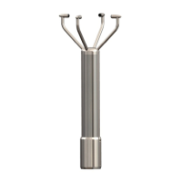
WindObserver II Option 1 RS422 output
or WindObserver II Option 2 RS422 output and analogue outputs
or WindObserver II Option 3 RS422 output and de-icing
or WindObserver II Option 4 RS422 output, analogue outputs and de-icing
and Installation kit (comprising a gasket and four Stainless Steel screws)
and WindObserver II Quick Start Guide
and WindObserver II User Manual (this manual)
and Integrity Check Chamber (ICC) (Optional)
5.2. Installation requirements
Host system - One of the following:
PC with an internal or external interface compatible with the RS422 output from
the WindObserver II.
Gill WindDisplay.
Other equipment with I/O compatibility to the WindObserver II option selected.
For example if the unit has Analogue outputs, a Data Logger, Chart Recorder, or PC
fitted with an ADC card.
Networking - Multiple WindObserver II units can be networked
Software - One of the following:
WindCom – A user-friendly package providing easy configuring of the
WindObserver II, for use on PCs running under Windows™ 98, 2000 or XP.
Available to customers as a free download from www.gill.co.uk.
HyperTerminal (for Windows™ 9x and later), or Terminal (Windows™ 3.n),
normally already installed on a PC.
Other Terminal Emulation software packages
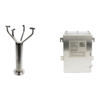
Cable and Junction box
To connect between the WindObserver II and the host system. The unit is supplied with a
2m or 10m flying cable, requiring a mast mounted junction box (not provided) for onward
connection.
See Section 6.4 for connection details
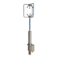
The flying cable must be retained with a cable tie within 150mm of the base of the
anemometer.