Gill Instruments Ltd
_____________________________________________________________________________________________________________
________________________________________________________________________________________________
WindObserver II Page 15 Issue 18
Doc. No. 1390-PS-0004 January 2009
Networking units
Before coupling units into a network:
Each device must be configured with a unique Unit Identifier (letter A to Z)
however in multi drop systems it could be advised to avoid using letters A-F,
KMN and P as they could appear in the data string.
Unit must be set for half duplex mode (E2 setting) see Para 8.3).
It must be configured to a tri-state polled mode M3 or M4.
See also Section 9 - Configuring
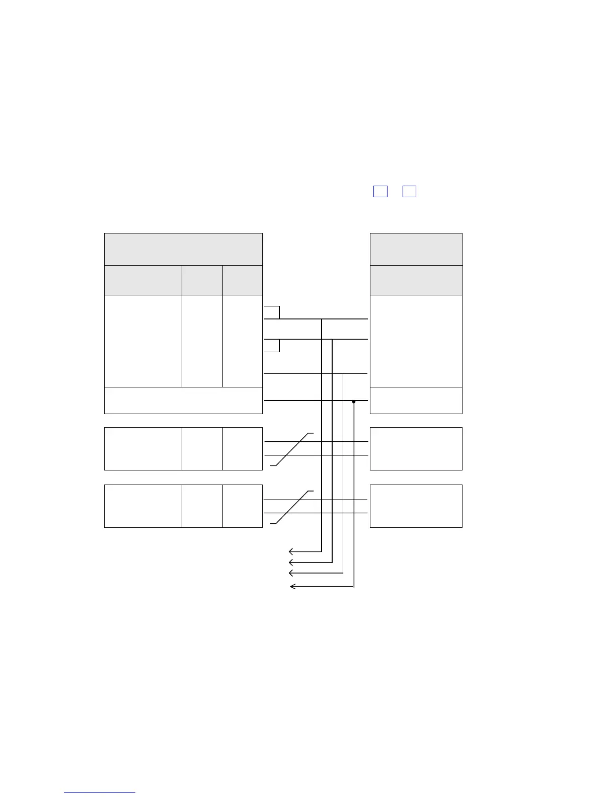
T / RXB (+)
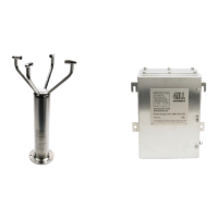
WindObserver II
9 pair cable
Signal names
Pair
no
Colour
TXB (+)
RXB (+)
TXA (-)
RXA (-)
Digital OV
1
2
1
2
4
CONNECTED INTERNALLY
PC with RS485
card
Signal names
Signal Ground
Ground (Earth)
Supply V+
Supply V-
3
red
black
Heater +
Heater -
5
yellow
black
DC Power
supply 9-30V
see section 6.6
+
-
Heated power
supply
see section 6.6
+
-
Cable - 2 or 3
twisted pairs
Screen and
drain wires
green
white
black
black
blue
T / RXA (-)
.
.
.
.
.
To Next Unit
Note: Each unit in the network will require its own power supplies.
Please refer to section 8.3.