Gill Instruments Ltd
_____________________________________________________________________________________________________________
________________________________________________________________________________________________
WindObserver II Page 10 Issue 18
Doc. No. 1390-PS-0004 January 2009
6. INSTALLATION
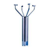
Do NOT remove the black “rubber” transducer caps. Take care not to knock
the four Transducer arms. All the time the WindObserver II is not in its final
location, it should be protected from damage by keeping it in the original
packaging as long as possible, treating it as a delicate instrument.
If an Intrinsically Safe (IS) device is required, the I.S. WindObserver must be
used - the WindObserver II is NOT an IS device.
Warranty is void if the unit case is removed.
6.1. Installation Guidelines
The WindObserver II has been designed to meet and exceed the stringent standards listed
in its specification. Operating in diverse environments all over the world, WindObserver II
requires no calibration or adjustment whatsoever.
As with any sophisticated electronics, good engineering practice should be followed to
ensure correct operation.
Always check the installation to ensure the WindObserver II is not affected by
other equipment operating locally, which may not conform to current standards,
e.g. radio/radar transmitters, boat engines, generators etc.
Guidelines –
Avoid mounting in the plane of any radar scanner – a vertical separation of
at least 2m should be achieved.
Radio transmitting antennas, the following minimum separations (all round)
are suggested
• VHF IMM – 1m
• MF/HF – 5m
• Satcom – 5m (avoid likely lines of sight)
Ensure the product is correctly earthed in accordance with this manual
Use cables recommended by Gill, keeping the length below the maximum allowed
(See Section 6.3) Where the cables are cut and re-connected (junction boxes, plugs
and sockets) the cable screen integrity must be maintained, to prevent the EMC
performance being compromised.
Earth loops should not be created – earth the system in accordance with the
installation guidelines. (See Section 6.4)
Ensure the power supply operates to the WindObserver II specification at all times.
Avoid turbulence caused by surrounding structures that will affect the accuracy of the
WindObserver II such as trees, masts and buildings. The World Meteorological
Organisation makes the following recommendation:
The standard exposure of wind instruments over level open terrain is 10m above
the ground. Open terrain is defined as an area where the distance between the
sensor and any obstruction is at least 10 times the height of the obstruction.
When installing the unit degrease the unit and hold with lint free gloves to reduce the
build up of deposits.