Gill Instruments Ltd
_____________________________________________________________________________________________________________
________________________________________________________________________________________________
WindObserver II Page 19 Issue 18
Doc. No. 1390-PS-0004 January 2009
6.5. Analogue connections
When using the analogue outputs it is advisable to use a low pass filter to remove any high
frequency noise present.
The analogue signals can be susceptible to external interference if unprotected. The
anemometer cable has individual screens covering each channel’s signal wires. The
continuing cable connected to the anemometer must be of equal or greater cross sectional
area as the anemometer cable and must be individually screened or screened pairs.
Note that connections can also be made to a PC or other device as described in the
preceding section.
REFER TO SECTION 9.5 the T command selects Voltage or Current Output on Channels
1-3.
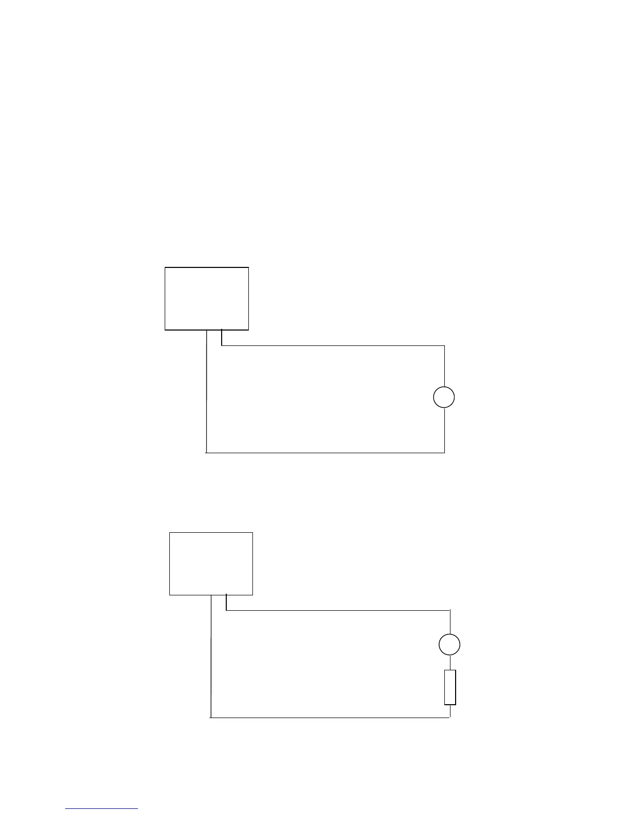
Analogue Voltage Output Connections (5v or ±
±±
± 2.5v)
Analogue Connections for 4-20mA output
Important – When using the current outputs, the output loads on each channel
MUST be less than 300 ohms, including cable resistance.