Electrical Contact Control
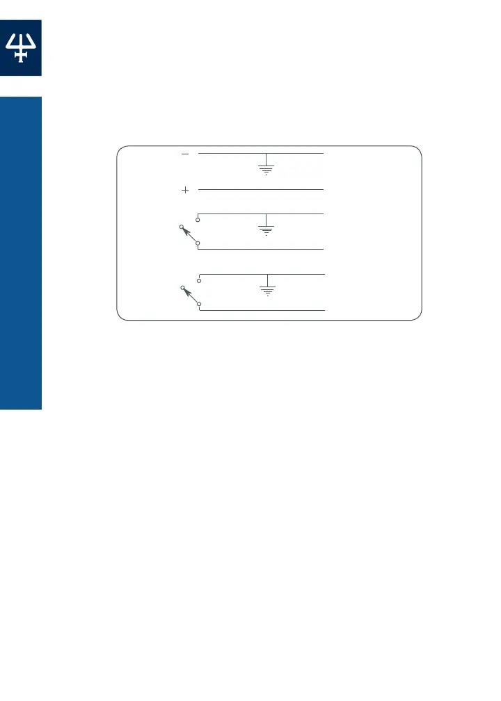
There are two contact inputs and one analog input available on the
8-pin terminal block connector. These TTL low-level active inputs
(0–5V) have a threshold of 2 Volts and are pulled up to 5 Volts with a
high impedance. The connection diagram is shown below.
START
STOP
ANALOG
INPUT (0-5 V)
0-5 V, giving 0 - 100%
of the selected speed
0 V Active (Start)
0 V Active (CCW)
5 V Inactive (CW)
5 V Inactive (Stop)
Pump Speed
Start/Stop
Direction
Control
0
9
Start/Stop Input (ContactInput)
The pump can be started by closing the start/stop input, and stopped
by opening it. The input is closed by shorting pin 3 to ground (pin 2,
4, or 8). Closing this input starts the pump in the direction selected
by the Direction Control input at the speed defined by the Analog
Input. When the pump is started using this input, the keypad has no
effect until the Start/Stop contact is opened again.
Direction Control (Contact Input)
When the Direction Control contact is opened, the pump rotates
in the forward direction (clockwise). When this contact is closed,
the pump rotates in the reverse direction (counter-clockwise). The
direction of rotation may be changed while the pump is running, in
which case the transition is immediate.
54
ELECTRICAL CONTACT CONTROL | MINIPULS® 3 PERISTALTIC PUMP
ELECTRICAL CONTACT CONTROL
 Loading...