5 Installation
10 Installation and maintenance instructions ENERGY 0020177748_03
5 Installation
5.1 Preparing for installation
Danger!
Risk of scalding and/or damage due to
incorrect installation leading to escaping
water.
Mechanical stresses in the connection pipes
may lead to leaks.
▶ Install the connection pipes such that they
are free from mechanical stress.
Caution.
Risk of material damage caused by corro-
sion
Due to non-diffusion-tight plastic pipes in the
heating installation, air gets into the heating
water. Air in the heating water causes corro-
sion in the heat generator circuit and in the
product.
▶ If you use non-diffusion-tight plastic pipes
in the heating installation, ensure that no
air gets into the heat generator circuit.
Caution.
Risk of material damage caused by
residues in the pipelines.
Welding remnants, sealing residues, dirt or
other residues in the pipelines may damage
the product.
▶ Flush the heating installation thoroughly
before installing the product.
Caution.
Risk of material damage due to heat trans-
fer during soldering.
▶ Only solder connectors if the connectors
are not yet screwed to the service valves.
Caution.
Risk of material damage caused by
changes to the pipes that have already
been connected.
▶ Only bend connection pipes if they have
not yet been connected to the product.
Caution.
Risk of damage caused by incorrect gas
installation.
Excess test pressure or operating pressure
may cause damage to the gas valve.
▶ Check the leak-tightness of the gas valve
using a maximum pressure of 11 kPa
(110 mbar).
▶ Make sure that the existing gas meter is capable of
passing the rate of gas supply required.
▶ Install the following components:
– Drain cocks at the lowest points in the heating install-
ation (→ current version of "BS 2879")
– A heating pump in the heating flow
– A bypass that is at least 1.5 m away from the product
– A stopcock in the gas pipe
– Where applicable, a flow regulator valve to adjust the
flow rate
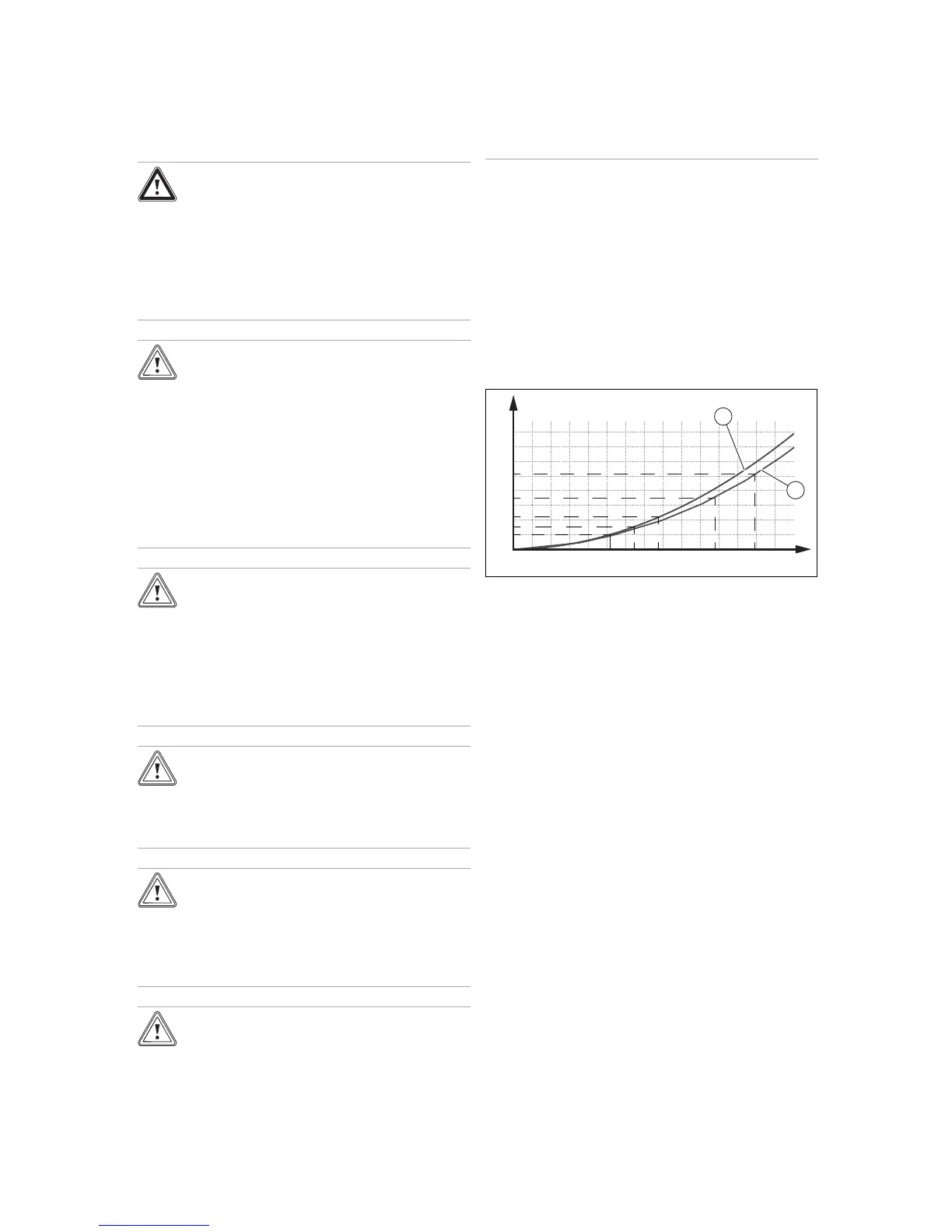
Pressure loss
from the product
A Flow rate [l/h]
B Pressure loss [mbar]
1 Pressure loss 12r, 15r,
18r
2 Pressure loss 25r, 30r
The flow rate must not fall below the value in the diagram.
5.2 Installing the heating pump
▶ Only use pumps that have an in-rush current ≤ 10/15 A.
▶ When designing/selecting the pump, note the pressure
loss of the product.
▶ Install the pump in the heating flow.
▶ Install the pump upstream and downstream of the pump
isolation valves.
▶ Set the pump so that the temperature difference between
the flow and return is no more than 20 °C when the max-
imum flow temperature is set.
– The flow rate specified in the technical data is
reached.
 Loading...