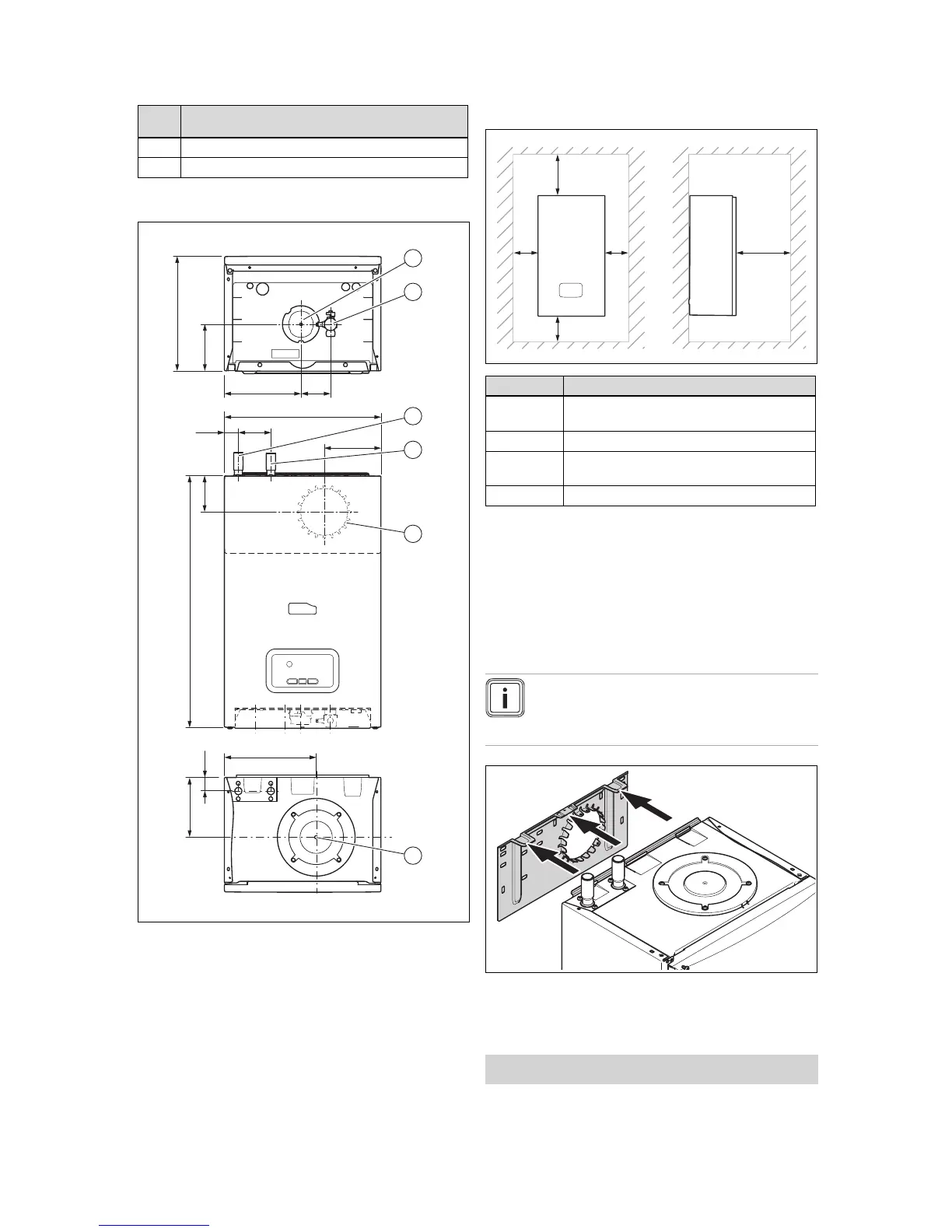
EasyManuals Logo

Glow-worm EASICOM 3 25r User Manual

Glow-worm EASICOM 3 25r
48 pages
To Next Page IconTo Next Page
To Previous Page IconTo Previous Page
Page #8 background imageLoading...
Page #8 background image
4 Set-up
8 Installation and maintenance instructions ENERGY 0020177748_03
Num-
ber
Description
1
Installation template
1 Enclosed documentation
4.4 Dimensions
112
183,5 71
375
7833,5
602
220
150
32,5
100
157,5
280
1
2
3
4
5
6
1 Condensate discharge
2 Gas connection
3 Heating return
4 Heating flow
5 Connection on the back
of the air/flue pipe
6 Connection on the top
of the air/flue pipe
4.5 Minimum clearances
CC
A
B
D
Minimum clearance
A 150 mm (top air/flue gas connection)
20 mm (air/flue gas connection on the rear)
B 150 mm
C 5 mm
(70 mm if the side panels ought to be removed)
D 600 mm
It is not necessary to maintain a clearance between the
product and components made of combustible materials that
go beyond the minimum clearances.
4.6 Using the mounting template
Use the mounting template to ascertain the locations at
which you need to drill holes.
4.7 Wall-mounting the product
Note
If you are using the rear air/flue connection, in-
stall the air/flue pipe before you wall-mount the
product.
1. Check whether the wall has sufficient load-bearing ca-
pacity to bear the operational weight of the product.
2. Check if the supplied fixing material may be used for
the wall.
Conditions: The load-bearing capacity of the wall is sufficient, The fixing
material may be used for the wall
Wall-mount the product as described.

Table of Contents

Questions and Answers:

Question and Answer IconNeed help?

Do you have a question about the Glow-worm EASICOM 3 25r and is the answer not in the manual?

Glow-worm EASICOM 3 25r Specifications

General IconGeneral
BrandGlow-worm
ModelEASICOM 3 25r
CategoryBoiler
LanguageEnglish

Related product manuals