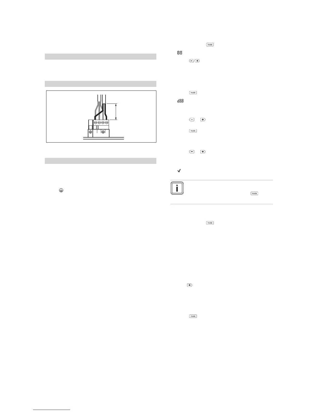
▶ Connect the controller to the main plug.
▶ Remove the bridge from the plug 24V=RT.
Conditions: 230 V 3-wire connection
▶ Ensure that the controller is designed for a maximum
rated current of 7 A.
▶ Connect the controller to the main plug X1.
– Terminal assignment: L ‑ line, N ‑ neutral conductor,
‑ earth
▶ Draw the operator's attention to the fact that the follow-
ing features are present with this type of installation.
◁ The frost protection function is deactivated. If the
product is installed in a room where there is a risk
of frost and it has not been protected by a room ther-
mostat, install an additional frost protection thermo-
stat.
◁ The pump programmes are not active.
◁ If the product is switched off, the display is switched
off.
◁ Each time the unit is started, the fan runs for
20 seconds.
◁ Residual heat in the heating return may result in the
product blocking the burner for 10 minutes.
4. Close the electronics box.
6 Operation
6.1 Using diagnostics codes
You can use the parameters marked as adjustable in the
table of diagnostics codes to adapt the product to the system
and customer requirements.
Overview of diagnostics codes (→ Page 26)
6.1.1 Activating diagnostics codes
1.
Press and hold the button for seven seconds.
◁
is shown in the display.
2.
Press the buttons to set the value.
◁ The access code (96) is reserved for the competent
person.
◁ The access code (35) is reserved for the customer
service.
3.
Press the button to confirm.
◁
is shown in the display.
6.1.2 Setting a diagnostics code
1.
Press the or button to select the diagnostics
code.
2.
Press the button to confirm.
◁ The value and/or status of the diagnostics code is
shown in the display.
3.
Press the or button to set the value.
4. If you allow the value to flash for three seconds, the
setting is automatically confirmed.
◁
is shown in the display for 1 second.
Note
You can manually confirm the setting at any
time by pressing and holding the button
for less than 3 seconds.
5. Proceed accordingly for all parameters that need to be
changed.
6.
Press and hold the button for 3 seconds to finish
configuring the diagnostics codes.
◁ The display switches to the basic display.
6.2 Displaying the status codes
The status codes display the product's current operating
status.
Status codes – Overview (→ Page 29)
6.2.1 Activating the status codes display
1.
Hold the button down for more than 7 seconds.
◁ S.XX is shown on the display, followed by the heat-
ing flow temperature, the internal system pressure
and the cylinder temperature (depending on the ver-
sion).
2.
Press the button to exit this menu.
◁ The display switches to the basic display.
 Loading...