12 Decommissioning the product
24 Installation and maintenance instructions ENERGY 0020177748_03
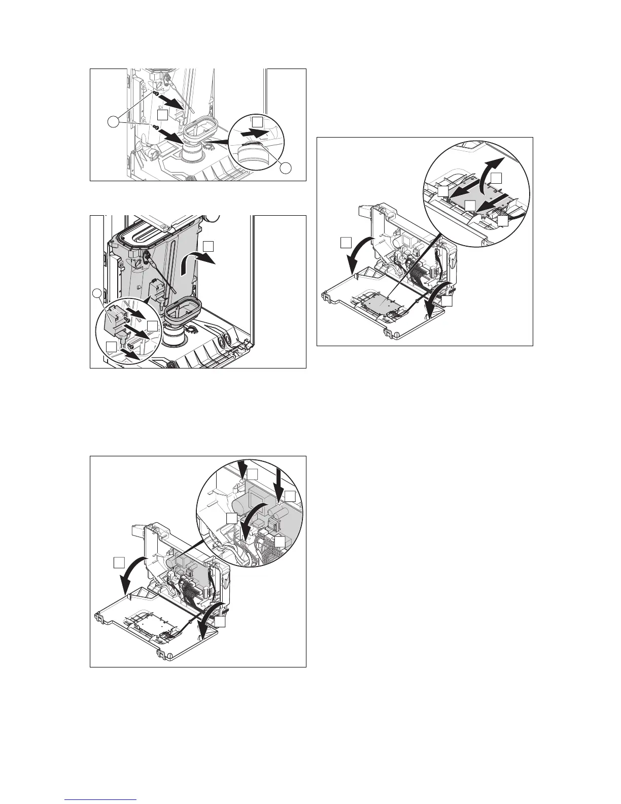
6. Undo the clip underneath the condensate tray (4).
7. Undo the two screws (3).
8. Lift the heat exchanger up slightly and remove it to-
gether with the condensate tray.
9. Remove the ignition transformer (5).
10. Replace all the seals.
11. Install the new heat exchanger in reverse order.
11.5.4 Replacing the main PCB
1. Open the electronics box. (→ Page 13)
2. Pull all of the plugs out from the PCB.
3. Undo the clips on the PCB.
4. Remove the PCB.
5. Install the new PCB in such a way that it clicks into the
groove at the bottom and into the clip at the top.
6. Plug in the PCB plugs.
7. Close the electronics box.
11.5.5 Replacing the PCB for the user interface
1. Open the electronics box. (→ Page 13)
2. Pull the plug out of the PCB.
3. Undo the clips on the PCB.
4. Remove the PCB.
5. Install the new PCB in such a way that it clicks into the
groove at the bottom and into the clip at the top.
6. Plug in the PCB plug.
7. Close the electronics box.
11.6 Checking the product for leak-tightness
▶ Check that the product is leak-tight. (→ Page 19)
12 Decommissioning the product
▶ Switch off the product.
▶ Disconnect the product from the power mains.
▶ Close the gas isolator cock.
▶ Close the cold water stop valve.
▶ Drain the product. (→ Page 22)
13 Customer service
For contact details for our customer service department, you
can write to the address that is provided on the back page,
or you can visit www.glow-worm.co.uk.
 Loading...