Service
50 312780K
Servicing Flow Meters Mounted
on Wall Panel
Coriolis Meter
1. Follow Before Servicing, page 40.
2. To remove and service the Coriolis meter, see man-
ual 313599.
G3000, G3000HR, or G3000A Meter
Removal
1. Follow Before Servicing, page 40.
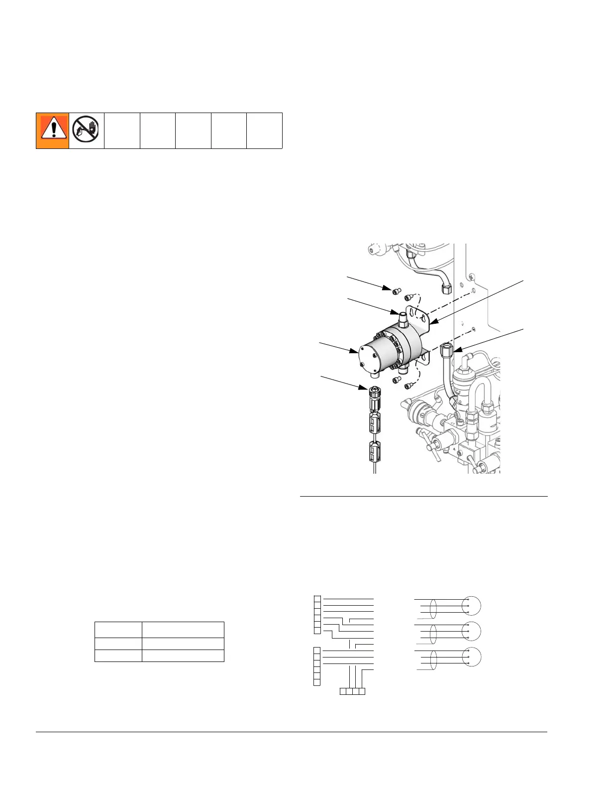
2. Unscrew cable connector (CC) from meter (M). F
IG.
23.
3. Unscrew four 1/4-20 screws (MS) holding the meter
mounting plate (MP). F
IG. 23.
4. Unscrew fluid line from meter inlet (P).
5. Unscrew meter (M) from dose valve connector (H).
F
IG. 23.
6. Service meter as instructed in the meter manual
308778.
Installation
1. Screw meter (M) securely onto the dose valve con-
nector (H), using a wrench.
NOTE: To avoid leakage, secure the meter (M) to the
dose valve connector (H) before connecting it to the fluid
station.
2. Secure meter (M) and plate (MP) to fluid station with
screws (MS).
NOTE: You must assemble the meter sensor to the
meter body before connecting the cable to the sensor
for the meter to function properly.
3. Connect meter cable (CC). See F
IG. 23.
4. Connect fluid line (P).
5. Calibrate meter as instructed in ProMix Operation
manual.
FIG. 23: G3000/G3000HR/G3000A Flow Meters
FIG. 24: Meter Cable Schematic
1
2
3
4
5
6
J3
PWR (RED)
COM (BLACK)
SIG (WHITE)
SHIELD/GRN
PWR (RED)
COM (BLACK)
SIG (WHITE)
SHIELD/GRN
PWR (RED)
COM (BLACK)
SIG (WHITE)
SHIELD/GRN
FLOW METER A
FLOW METER B
3X CABLE
FLOW METER SOLVENT
1
2
3
4
5
6
J12
GROUND
TERMINAL
*Connectors on Fluid Station Control Board
*
*
Cable Length
17C743 5 ft (1.52 m)
17C909 16 in. (406 mm)
 Loading...