Repair
Transformer Transformer
Transformer
Primary Primary
Primary
Check Check
Check
SeeElectricalSchematics,page94.
1.Checkwiresandtransformer:
a.SeeShutdown,page49.
b.ShutoffCB15.
c.Useanohmmetertotestforcontinuity
betweenterminals2and4ofCB15.Ifthere
isnocontinuity,checktransformerandwiring
betweenCB15andTB31locatedbehindthe
lowercover.Gotostep2.
2.ChecktransformerandTB31:
a.SeeShutdown,page49.
b.Removethelowercover.
c.Locatethetwosmaller(10AWG)wires,
labeled1and2,comingoutoftransformer.
Tracethesewiresbacktoterminalblocks
TB31.
d.Useanohmmetertotestforcontinuity
betweentwowires;thereshouldbe
continuity.
Transformer Transformer
Transformer
Secondary Secondary
Secondary
Check Check
Check
SeeElectricalSchematics,page94.
1.Checkwiresandtransformer:
a.SeeShutdown,page49.
b.Disconnect7pingreenconnectorfromTCM.
c.Useanohmmetertotestforcontinuity
betweenterminals6and7ontheTCM7pin
greenconnector.Thereshouldbecontinuity.
Ifthereisnocontinuity,checktransformer
andwiring.
d.Leave7pingreenconnectordisconnected
fromTCM.
2.Checktransformer:
a.Removelowercover.
b.Locatethetwolarger(6AWG)wires,labeled
3and4,comingoutoftransformer.Trace
thesewiresbacktoTB31.Useanohmmeter
totestforcontinuitybetweentwotransformer
wiresinterminalblockTB31;thereshould
becontinuity.
c.Reconnectthe7pingreenconnectortothe
TCM.
d.Applyincomingpowertosystem.
e.Toverifyvoltageonthesecondaryleads
ofthetransformer,measurebetweenthe
transformerleadslabeled3and4atTB31.
Verifythetransformeroutputvoltageis
approximately37.5%ofthesystemsupply
voltageforH-30andH-XP2systems
orapproximately50%ofsystemsupply
voltageforH-40,H-50,andH-XP3.For
example,witha240VACsystemsupply
voltagethetransformeroutputvoltagefor
anH-30orH-XP2wouldbe(.375x240V),
orapproximately90V;foranH-40,H-50,
orH-XP3itwouldbe(.50x240V),or
approximately120V.
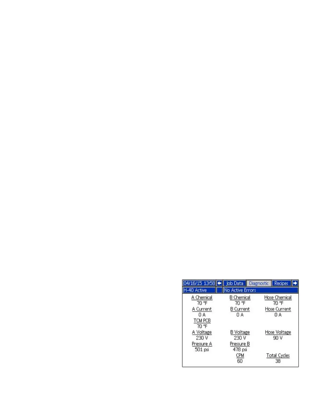
f.SeetheDiagnosticRunScreenontheADM.
TheDiagnosticRunScreendisplaysthe
transformeroutputvoltage(approximately
90or120VAC)under“HoseVoltage”.The
diagnosticscreenwillshowaHoseVoltage
of“0”voltsifthecircuitbreakerhasbeen
trippedfortheincomingpowertotheTCM.
Note
TheDiagnosticRunScreenis
disabledbydefaultandmustbe
enabledintheSetupscreens.
SeetheOperationmanualfor
instructions.
64 334946C
 Loading...


