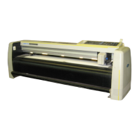
Do you have a question about the GRAPHTEC FC7000-160 and is the answer not in the manual?
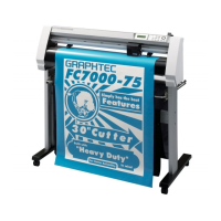
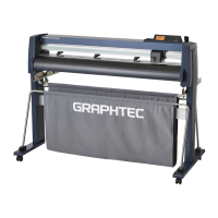
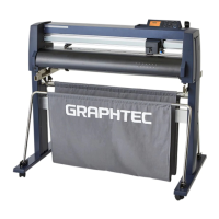
Identifies and describes the main parts of the plotter from front and rear views.
Instructions for assembling the media stocker and stand for the plotter.
Procedure for correctly mounting and securing a cutter pen in the pen holder.
Explanation of indicator lamps and function/position keys on the control panel.
Diagram illustrating the main and sub-menu structure for operating the plotter.
Details on various background settings like display language and command settings.
List of recommended parts for FC7000-75/100/130/160 models with part numbers.
List of recommended parts for FC7000MK2 models with part numbers.
Lists the specific tools required for various adjustment and maintenance tasks.
Identifies points requiring greasing or gluing and the recommended materials.
Procedures for detaching and reinstalling exterior covers like side and center covers.
Procedures for replacing various mechanical components of the plotter.
Detailed procedure for replacing the Y-motor.
Details on mechanical adjustments like belt tension and pinch roller pressure.
Procedures for electrical adjustments, including DIP switches and voltage checks.
Procedure to set and adjust the pen force for cutting and plotting.
Procedure to adjust the plotter's distance accuracy for precise cutting.
Checks the status of various sensors to identify potential issues.
Tests the status of each switch on the plotter's control panel.
Solutions for when the plotter does not turn on or display anything.
Troubleshooting steps for issues related to media loading and feeding.
Troubleshooting for common cutting issues like crooked lines or skipped cuts.
Lists and explains error messages and their corresponding solutions.
Lists parts related to the outer casing of the plotter.
Lists parts associated with the plotter's control panel assembly.
Lists parts that constitute the main frame of the plotter.
Lists parts related to the Y rail assembly.
Lists parts associated with the Y slider mechanism.
Provides block diagrams illustrating the overall system architecture.
Presents detailed circuit diagrams for various main board sections.
Block diagram illustrating the FC7000 series wiring connection.
| Model | FC7000-160 |
|---|---|
| Type | Cutting Plotter |
| Manufacturer | Graphtec |
| Max Cutting Speed | 1000 mm/s |
| Number of Tool Mounts | 1 |
| Buffer Size | 2 MB |
| Power Supply | AC 100-240V |
| Power Consumption | 150 W |
| Repeatability | ±0.1 mm |
| Interface | USB |
| Compatible Media | Vinyl, paper |
| Max Cutting Force | 5.88 N (600 gf) |
| Cutting Force | 0.49 - 5.88N (50 - 600gf) (38 steps) |
| Mechanical Resolution | 0.025 mm |
| Programmable Resolution | 0.025 mm |
